1 Introduction This article refers to the address: http:// The Vehicle License Plate Recognition (VLPR: V ehic le Licensee PlateRecognit iON) system acts as a dedicated computer vision system that automatically captures vehicle images and identifies license plates. This system can be applied to various occasions such as automatic road toll collection, parking lot management, stolen vehicle reconnaissance, door guard system, and intelligent transportation system. Vehicle license plate location is a difficult point in license plate recognition. Therefore, the research on road license plate location algorithm has important and practical significance. License plate recognition is a typical application example in the image processing technology that first divides the target and then recognizes it. Similar applications include the segmentation and identification of postal codes on envelopes, the automatic segmentation and identification of freight train model numbers, and the identification of text. Although the vehicle license plate recognition system is a dedicated system for license plate recognition, its research will promote the research of similar problems mentioned above. There are many methods for license plate location, such as mathematical morphology-based positioning methods: color-based positioning methods, which mainly use color space information to achieve license plate location, including color edge algorithm, color distance, similarity algorithm and Edge-based color pairing method; method for extracting license plate based on genetic algorithm: vehicle license plate location method based on neural network. Aiming at the advantages and disadvantages of various license plate location algorithms, a license plate location algorithm based on DCT changes is proposed. This method extracts a new feature of license plate area based on weighted frequency in DCT data, and then adopts adaptive threshold classification and adopts projection based method. The license plate segmentation method directly realizes the rapid positioning of the license plate in the DCT domain. The method can make the positioning rectangular frame compactly surround the license plate area, effectively reduce the false detection rate, and the operation complexity is low, which is beneficial to realize the rapid positioning of the license plate in the complex background. 2 license plate location algorithm 2. 1 discrete cosine transform The discrete cosine transform (DCT) is the symmetry of the Fourier transform. The image boundary fold operation is used to transform the image into an even function form. Then, the image is subjected to two-dimensional discrete Fourier transform, and the transformed result will only contain the cosine term. Therefore, it is called discrete cosine transform. The DCT can describe the image as the sum of the sine values ​​of different amplitudes and frequencies. For a typical image, DCT has such a property: Many important visual information about the image is concentrated in a small fraction of the coefficients of the DCT transform. The two-dimensional DCT of an M N matrix A is defined as follows: 2. 2 Feature extraction based on DCT domain For color images, the image preprocessing section first removes the color of the input image and performs grayscale. Use the RGB space to grayscale conversion formula to get the grayscale image of the license plate, namely: The position of the coefficient obtained by DCT transformation of the preprocessed image and its amplitude reflect the spatial frequency and energy of the transformed image. Here, the image is divided into sub-blocks, and the size of the sub-block is 8 8, and each of the 8 8 sub-blocks is DCT-transformed so that the energy is concentrated by frequency, and 64 transform coefficients are obtained, respectively representing corresponding different fundamental frequency components. the size of. If the DCT coefficients of 8 8 are divided into 4 regions such as 0 region, 1 region, 2 regions, and 3 regions, each region represents the direction of different textures: the 0 region represents the DC component (that is, the average of 8 8 subblocks) Value), area 1 represents the vertical texture (ie, the frequency change in the horizontal direction), area 2 represents the oblique texture (ie, the frequency change in the oblique direction), and area 3 represents the horizontal texture (ie, the vertical direction) Frequency change). Since the license plate character area has a special line structure, it can basically be classified into a horizontal, vertical, and oblique line combination. In the image, these lines mainly show special texture features, and their gray level and background are quite different, that is, the edge changes are more severe, and the vertical, oblique and horizontal texture features are obvious. In the DCT domain, the coefficient values ​​in the middle and high frequency parts of the 1, 2, and 3 regions of the graph are large, that is, the transform coefficients of the vertical lines are mainly concentrated in the 1 region, and the transform coefficients of the oblique lines are mainly concentrated on Zone 2 (1st and 3rd districts also have a certain distribution), the transformation coefficient of the horizontal line is mainly concentrated in Zone 3, which is the texture feature of the license plate characters contained in the image in the DCT domain. It can be seen that the special structure of the license plate character area enables it to exhibit richer mid- and high-frequency DCT components in the DCT domain. At the same time, the license plate character area shows obvious directional information in the DCT domain. Considering the above two points, a weighted frequency feature based on DCT sub-blocks (W 8ed Frequency, WF) is used to nonlinearly weight the DCT components in different directions, as shown in equation (5), thereby making the license plate character area The features are more obvious. 2. 3 classification processing When classifying, if the contrast between the license plate and the background in the image is low, the WF value at this time will be relatively small; in addition, the background of the non-license plate area rich in high-frequency information often has a large WF value. Therefore, if a fixed threshold is used, it is not conducive to the extraction of the low-contrast license plate area, and it is also easy to mistake the high-frequency rich background for the license plate area. Therefore, the algorithm uses the adaptive threshold method for classification, and the threshold is set as shown in equation (6). 2. 4 smooth denoising In the classified binary marker map, there are usually some scattered noise points, and there is only one real license plate area. Too many noise points often interfere with the projection of the license plate area, causing the positioning frame to be larger than the actual license plate area, or manufacturing fake License plate area. Therefore, before segmentation, the classification result graph needs to be smoothed and denoised. The usual noise is the background of some objects with rich edges or textures. The shapes are mostly irregular and the distribution is sparse. The statistical filtering method can reduce the influence. The specific method is as follows: Count the number of pixels in each candidate area, and find When the number of pixels in the candidate region is less than a certain value (1/4 of the maximum number of pixels in the candidate region is used in the algorithm), the region is considered as a noise region, and is removed. For a small number of pits and discontinuities that may be present in the candidate license plate area, smoothing can be performed by the run-length smoothing algorithm. The so-called run-length smoothing algorithm detects the distance between black pixel points on the same scanning line. When the length of the blank run between two adjacent black pixel points is less than the threshold value, the blank run between the two points is used. Fill in all black. Consider a run L = (P 1, P 2, ..., P i, Pi + 1, ..., P j-1, P j, ..., Pn ) on a horizontal scan line; where run L1 = ( P1, P2, ..., P i ) and L 3 = (Pj , ..., P n ) are 0-runs (ie black pixel runs), and L 2 = (Pi+ 1, ......, Pj-1) 1 - Run (ie white pixel run). When the length j-i-1 of L2 is less than the set threshold T, the two black runs L1 and L3 are connected to smooth all the pixels of the run L2 to black. In this algorithm, the run-length smoothing algorithm is used twice, that is, once in the horizontal direction and in the vertical direction. The processed image is shown in Figure 3. 2. 5 projection segmentation After the above operation, the actual license plate will be included in a certain area. In order to accurately position the license plate, the projection method is used to segment the license plate area in the image quickly, and the false detection rate is low. For the denoised marker map, firstly project it horizontally, then analyze the projection value to determine the horizontal baseline, and then vertically project between the horizontal baseline to determine the vertical baseline. This will allow you to initially locate the license plate area. The baseline is generated according to the following rules: First, a threshold T is set, the projection value smaller than the threshold is set to 0, the projection value larger than the threshold is set to 1, and then when the adjacent projection values ​​are 0 and the other is 1, That is, there is a baseline at the non-zero projection value. Two projections, horizontal and vertical projection, were performed in the algorithm. Once you have determined the horizontal and vertical baselines, you can draw a rectangular frame in the image to mark the license plate area. In addition, in order to make the rectangular frame tightly surround the license plate area, before drawing the baseline, first determine whether the sum of all the pixel values ​​on the baseline of the rectangular frame is zero. If it is zero, move the baseline to the position near the center of the rectangle until each baseline. The sum of all pixel values ​​on the top is not zero. The final positioning result of the algorithm is shown in Figure 4. 3 Conclusion The algorithm obtains the DCT coefficients by performing discrete cosine transform (DCT) on the car image, and calculates the weighted frequency features. Then the adaptive threshold method is used to realize the rapid classification of the license plate area/non-license plate area. After smoothing and filtering, the projection is utilized. The method realizes the positioning of the license plate area, effectively reduces the false detection rate, and has low computational complexity, which is beneficial to realize the rapid positioning of the license plate area in the complex background. After many experiments, the algorithm has a high correct detection rate, and some experimental results are shown in Figure 5.
Ni-Mh Battery is a kind of long shelf life battery ,it has high capacity and large current ,which can replace traditional dry cells ,take examples as below :
* This is
high performance rechargeable Lithium Ion battery with instantaneous start up;
* Durable
high impact plastic housing;
* High
capacity, performance verified, hermetically sealed, lithium-ion cells;
*
Protection against short circuit and improper charge;
* High
reliability due to all welded Construction;
* Unit
contains safety vented cells;
* 100%
final testing;
*
Replacement battery for Tait Orca
5000/5010/5020/5030 series two way radios.
Item Specification
Chemistry: Ni-MH
Voltage: Typical: 7.4V
Nominal
Capacity: 2000mAh at 400mA to 6V
at 23℃
Operating
Temp: -20 to +55 ℃
Storage
Temp: -30 to +45 ℃
Exterior/Housing: Hard Plastic Case
APPLICATIONS:
* Tait Cougar
400; M A-Com Cougar 400; M A-Com Cougar
6000P; M A-Com Cougar 625P; M A-Com Panther 400; M A-Com Panther 600; Tait Orca
5000; Tait Orca
5010; Tait Orca
5020; Tait Orca
5030; Tait Orca
5035; Tait Orca
5040; GE, Ericsson Cougar 400; GE,
Ericsson Cougar 6000P; GE, Ericsson Cougar 625P; GE, Ericsson Panther 400; GE, Ericsson
Panther 600.
Ni-Mh Battery,Rechargeable Ni-Mh Battery,Ni-Mh Rechargeable Battery,Ni-Mh Universal Battery YFJ TECHNOLOGY (HK) CO.,LIMITED , http://www.yfjpower.com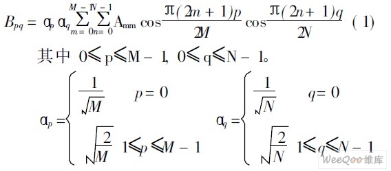
The value Bpq is called the DCT coefficient of A. DCT is a reversible transformation, and the inverse transformation is defined as follows: 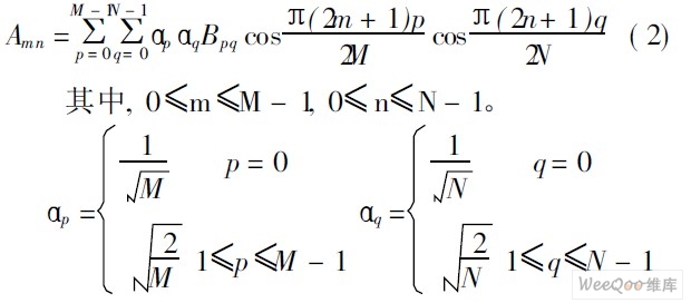
The DCT inverse transformation equation can be understood as: The matrix A of any M N can be written as M N in the form of the sum of the functions shown in equation (3): 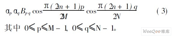
These functions are called DCT basic functions. 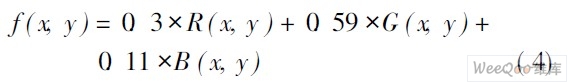
Where f ( x, y ) is the gray value of the pixel at ( x, y ) position, R ( x, y ), G (x, y ), B ( x, y ) is the input color image at ( x, y The color information corresponding to the red, green, and blue colors of the position pixel. 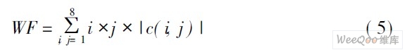
Where c(i, j) is the DCT coefficient of the i-th row and the j-th column of the 8 8 blocks; i takes 1~8; j takes 1~8, and Figure 1 shows the input vehicle image and its corresponding WF feature map. It can be seen that the WF value of the license plate character area is significantly higher than the background. 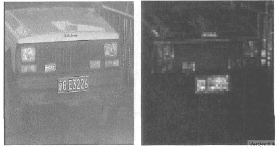
Figure 1 Input image and its WF feature map. ![]()
Where aver is the average WF value of the entire image, max is the maximum WF value of the entire image, m in is the minimum WF value of the entire image, and k is the empirical value, which can be classified according to formula (7). 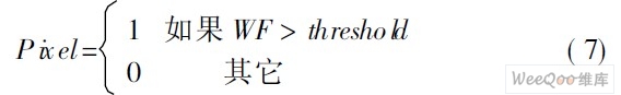
Figure 2 is a classification result graph. It can be seen that a large amount of background is removed and the license plate area is well extracted. 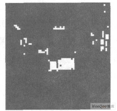
Figure 2 Classification result graph. 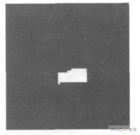
Figure 3 After smoothing the denoising process. 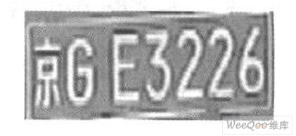
Figure 4 Positioning result map. 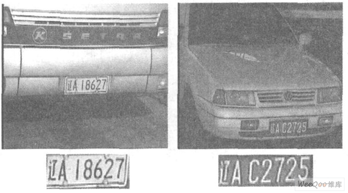

•