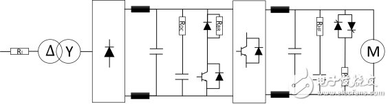
Centralized power generation technology is undergoing an innovation. Traditional power plants, such as coal, gas and nuclear power plants, are being replaced by renewable, decentralized solutions such as wind, solar or biomass power plants. The latter type of power plant usually follows the same principle, that is, using renewable energy sources (solar, wind, and biomass) and generating DC or AC voltage or current through one or more transition processes. Since energy producers are dispersed, more and more electricity is no longer fed into the high-voltage power system, but rather is fed into medium- and low-voltage power systems. Therefore, in the future, there will be an increasing need for smart power system management using energy storage devices to meet peak load requirements in a variety of ways. The core component of these power plants is a power converter that can provide the generated electrical energy to the power system or consumer in a synchronized manner and with the right quality. These power plants not only impose extreme demands on individual components, but they must also achieve a service life of about 20 years under difficult environmental conditions. In recent years, the focus of power converters has shifted to higher power densities and higher switching frequencies for semiconductors. The first development made it possible to improve the price/performance ratio because it increased the output power while keeping the system cost almost unchanged. The second development increases system efficiency because system losses are reduced due to increased switching frequency. Figure 1: Conceptual circuit diagram of a power converter The power converter moves from the input side (left) to the consumption side (right) in the circuit diagram, and has a resistor (RI) for limiting the charging current to protect the capacitor against interference. After energization, the resistor must accept a large amount of pulse energy. This application of energy flow or energy occurs in a very short time of capacitive charging, and usually only once (appearing during start-up and without periodicity). This places special demands on the resistor technology used. Adiabatic boundary conditions exist because of the short duration of the pulse. Therefore, this energy is only applied to the acTIve material of the resistor, and does not propagate through the entire resistor by heat conduction. Compared to thick film or thin film technology, wirewound resistors are of high mass and therefore accommodate high pulse energy and continuous power. But the low power converter uses all the resistor technology. These include SMD-MELF thin film resistors, LTO thick film resistors and the wirewound resistors mentioned above. If the power is high, the series or parallel winding resistances can be combined into printed circuit board (PCB) components (G200, AC, RS, CW, FS, and Z300). At powers above 50 W, there are many special wirewound resistors (such as GWK, GWS, CSxx, FST, FSE, EDGx, RSO, and GBS series) or thick film resistors (such as LPS or RPS on the heat sink) due to the extremely diverse Connection options, which can be installed away from the PCB) are available. After the AC voltage is converted to the appropriate voltage level, the B6 bridge is used to adjust the AC voltage and then the inductor is used to suppress the interference. On the one hand, the series connection of the DC link resistor (RDC) and the DC link capacitor is used to limit the charging current of the DC link capacitor. This current produces a relatively high but infrequently occurring pulse load. On the other hand, the series is used to suppress harmonics in the DC link circuit, which is equal to a continuous load (because of the continuously repeated pulse train). Therefore, the resistor used must be limited to withstand continuous power and pulse power. The latest power converters have the option of providing capacitive or inductive reactive power to power systems or power consumers. This is done by increasing or decreasing the DC link circuit voltage. This increase is achieved using an internal boost converter or directly at the input location of the power converter. A chopper resistor (RBR) is used to reduce the DC link circuit voltage by converting excess energy into thermal energy. Power MOSFETs, IGBT modules or thyristors provide a resistive switching function. Power MOSFETs and IGBT modules are capable of high frequency switching operations, but thyristors only support low frequency operation. These power switches connect a chopper resistor when the DC link circuit voltage is at risk of exceeding a specified maximum. After the DC link circuit voltage drops due to this operation, the chopper resistor is turned off again. These chopper resistors are simple to install and have a wide range of connection options with power dissipation of 100 W - 1000 W. In this case, the combination of chopper resistance and crowbar resistor is often found. In the event of a failure of the downstream component, this combination makes it possible to completely dissipate the energy of the DC link into the resistor (RBR), thereby preventing damage to the power converter. Here you can choose a steel grid or steel plate resistor whose main component is steel. For these types of resistors, extremely diverse alloy steel sheets have a ripple structure, and by cascading them, resistance, continuous power, pulse power, and maximum surface temperature can be set as needed. Ceramic or mica materials can be used for insulation between steel sheets. In addition, these plate resistors have a very low inductance, so no additional voltage spikes are generated during switching. Steel grid resistors (such as Vishay GREx) are suitable for high continuous power due to natural convection cooling provided by their large surfaces or the use of fans. The maximum achievable heat dissipation is limited only by the available installation space and fan output in this case. However, if more power is required and the insulation space is smaller, water-cooled resistors such as the Vishay WCR series can be used. In addition to the transient input surge current, filtering, and the limitations of the described DC link circuit matching, the DC voltage is converted to an AC voltage having a variable frequency and pulse width by the illustrated H-bridge circuit. The filter resistor (RHF) and the series output capacitor are used to suppress harmonics at the output stage. In addition, RHF also has the effect of limiting the charging current of the filter capacitor. Wired resistors with capped (such as the GWK and FVT series) are suitable for filtering applications due to their ease of installation and their high pulse power and continuous power. The difference in this series is that its robust glass insulation has resistance to moisture and chemical cleaning materials. The GWK and FVT series also make it easy to achieve low inductance. In this respect, two resistance wires are wound around the resistor body in a double-strand manner. According to the superposition principle, the magnetic fields generated by the counter currents cancel each other out. Next is the rod resistance (RCR) - if they have not been placed in the DC link. As mentioned earlier, the purpose of this resistor is to prevent the surrounding components from being overloaded in the event of a fault. The three resistors of RDC filter resistor, RBR chopper resistor and RHF filter resistor are very helpful for optimizing the efficiency of the optimized system. In the case of high speed switching components such as IGBTs or power MOSFETs, it is necessary to carefully design these resistors to achieve low inductance. Incorrect selection of resistors can result in resonant circuits due to parasitic inductance and capacitance. These circuits generate peak voltages that overload or damage semiconductor components. In addition, the parasitic inductance "rounds" the signal waveform, which makes it impossible to produce a rectangular pulse with a steep rising edge. In addition, this has a negative impact on the power and efficiency of the entire circuit. For all of the applications mentioned in this article, Vishay offers a corresponding solution with different resistance technologies. In addition, Vishay also has suitable power capacitors that use high quality components to ensure the long-term efficiency and performance of the converters required. New Arrival or New Style Disposable ecig have a completely enclosed design, reducing the need for charging and replacing cartridges. The no-charge design also reduces the occurrence of faults. It is understood that with rechargeable e-cigarettes, each cartridge needs to be charged at least once and the battery efficiency is extremely low, while the design of disposable ecig can solve this problem very well. New Arrival Disposable E-Cigarette,New Arrival Mini E Cigarette,New Arrival Electronic Cigarette Customizing,Rechargeable E Cigarette Shenzhen E-wisdom Network Technology Co., Ltd. , https://www.globale-wisdom.com