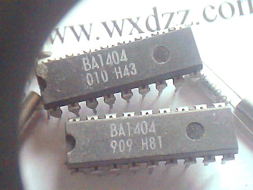
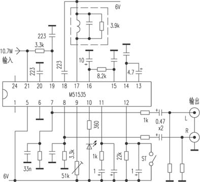
The principle diagram of the transmitter is shown in Figure 2. The core part is a stereo transmitting integrated circuit BA1404, which is packaged in an 18-pin dual in-line package. It includes left and right channel amplifiers, balanced modulator, and 19KHZ pilot transmission. Devices, radio frequency oscillators, radio frequency amplifiers and other circuits, Figure 1 is its internal block diagram. The stereo audio signal output from the computer and so on is input from the CZ2 socket. After the two audio signals pass through C10, C11, R4, and R5 to form a pre-emphasis network, they are coupled to pins 1 and 18 of IC1 through C4 and C5. The internal circuit forms a signal generator. The oscillating signal passes through a frequency divider to generate a 19KHZ pilot signal, and the other is used to encode the stereo audio signal. The encoded signal is output by pin 14 together with the pilot signal output by pin 13 Form a stereo composite signal, and send it to the 12th pin to modulate the high-frequency oscillation signal. The modulated RF signal is internally amplified and output by the 7th pin. The RF power amplification composed of Q1 and peripheral components further amplifies the FM signal. , And finally transmitted into the air by the TX antenna. The red LED1 not only serves as a working indicator light, but also serves as a voltage regulator for IC1, providing IC1 with a regulated DC voltage of about 1.9V. Although the operating voltage of the machine is relatively low, it can meet the listening needs in the range of tens of meters to 100 meters. If it is matched with a high-sensitivity FM radio, the transmission distance can be increased. If you need more transmission power, you need to connect a more powerful amplifier. The assembly of this circuit can be carried out with reference to the assembly drawing of FIG. 3 and the printed board drawing of FIG. 4. Check the components according to the component list. If there is an oxide layer on the pins, they should be scraped off with a knife to facilitate manual soldering. Since this circuit works in a high-frequency state, the component pins should be as short as possible during soldering to reduce the influence of distributed capacitance on the circuit. Antenna TX can be replaced by a section of 80-100cm wire (the antenna is not included in the kit by default, please contact this site if you need a rod antenna). After checking, you can connect two No. 5 batteries to CZ1. At this time, the red LED1 lights up, connect the audio signal source to CZ2, find an FM stereo radio, put it nearby, and search within the frequency of 88-108MHZ If the signal of this transmitter is found and there is no conflict with the frequency of the local broadcasting station, you can appropriately distance the distance and dial L2 to make the transmission distance the farthest and the sound quality is the best. Finally, seal L1 and L2 with wax , The production can be completed. In most cases, it can be a one-time success. If no signal is found, you can dial L1 (compressed or stretched) appropriately to make the transmission frequency of the machine enter the reception range of the radio, and then repeat the above process, if you can not enter the range of 88-108MHZ, you can check whether the component assembly Incorrect, whether the component is damaged, you can also try to add a welding capacitor C 'with a capacity of 10-30P, or replace C15 to reduce the capacity of C15. I wish you a successful production! Component list Part number Nominal value Quantity Part number Nominal value Quantity Part number Nominal value Quantity R1 130 1 C1 100U 1 IC1 BA1404 1 R2 R3 1.4K 2 C2 0.01U 1 Q1 9018 1 R4 R5 47K 2 C3 C4 C5 C6 10U 4 X1 38KHZ 1 R6 R7 27K 2 C7 220 1 L1 L2 Φ5  5T 2 R8 2.7K 1 C8 C9 C10 C11 C12 C13   C14 1000 7 CZ2 Φ3.5 seats 1 R9 150K 1 LED1 Φ3 red 1 R10 22K 1 Printed board 1 C15 82 1 C16 C17 C18   C19 15 4 Follow WeChat Download Audiophile APP Follow the audiophile class related suggestion Every electronic lover has the experience of electronic production, starting from ... The core device of this circuit (see Figure 5) is the stereo dedicated chip BA1404. Many FM stereo modules FM radio's ultra-long-distance high-fidelity reception FM (FM) radio reception is a hot topic in recent years, especially last year, this is because tune ... '+ data.data.username +' '; dom + =' Fpc Connector,Straight Pin Fpc Connector,Gold-Plated Straight Pin Fpc Connector,Conventional Fpc Connector Shenzhen Jinyicheng Electronci Technology Co.,Ltd. , https://www.jycconnector.com
Operating voltage 3V Current consumption 10mA Pilot frequency oscillation 38KHz Channel separation 45dB Operating temperature -20 ℃-+ 50


![[Photo] FM microphone production tutorial](http://i.bosscdn.com/blog/20/06/41/5204336666.jpg)
'+ data.username +'
'+ data.username +'
'; dom + ='
'; $ (' # follow_list '). append (follow_user);} if (data.status == "failed") {alert (data.msg);}});} else {// Unfollow if ($ ( this) .attr ('id') == 'cancelFollow') {$ .post ('/ d / user / cancelFollow', {tuid: article_user_id}, function (data) {// Data format returned: if (data .status == "successed") {follow_wrap.html ('Follow'). attr ('id', 'follow'). css ('background', '# f90'); $ (". followNum strong"). html (-getFollowNum); $ ('# follow_list .face'). each (function () {var target_uid = $ (this) .attr ('data-uid'); if (target_uid == now_uid) {$ ( this) .remove ();}})} if (data.status == "failed") {alert (data.msg);}}); return false;}}});});}); / * var myface = "{$ _super ['uid'] | avatar}"; var myname = "{$ _super ['username']}"; var article_id = {$ article ['id']}; var article_user_id = {$ article ['mid']}; // Article author ID $ (function () {<notempty name = "clearnum"> // Reduce the number of reminders var count = parseInt ($ ("# noticeCount"). html ()); count = count-{$ clearnum}; $ ("# noticeCount"). html (count); if ( count
Interesting and informative information and technical dry goods
Create your own personal electronic circle
Lock the latest course activities and technical live broadcast
comment
Publish
[Photo] FM microphone production tutorial
Posted at 2006-04-15 20:43 • 357 views
FM stereo transmitter and BA1404 application
Published on 2006-04-15 20:38 • 1731 times read
Ultra-long-range high-fidelity reception of FM broadcast
Published on 2006-04-15 19:21 • 1254 times read