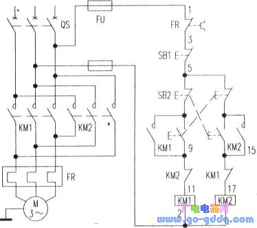
The reversible operation circuit of a railway signal motor is illustrated in the figure below. In this diagram, FR represents a thermal relay, which primarily serves as an overload protection device. To enable the motor to rotate both forward and backward, two contactors, KM1 and KM2, are used to reverse the phase sequence of the three-phase power supply connected to the motor. However, it is crucial that these two contactors do not operate simultaneously, as this would cause a short circuit. Therefore, an effective interlock mechanism must be implemented in the circuit. Figure 4 shows a control circuit that allows the motor to operate in both forward and reverse directions, using a double interlocking system involving both buttons and contactors. The interlocking mechanism works as follows: (1) Contactor Interlock: The coil circuit of KM1 is connected through the normally closed auxiliary contact of KM2, and vice versa. When the forward contactor KM1 is energized, its normally closed auxiliary contact opens, cutting off the power supply to KM2. This ensures that KM2 cannot be activated while KM1 is active. Similarly, KM2 must be de-energized before KM1 can be turned on, preventing any simultaneous activation that could lead to a short circuit. This connection is known as the contactor interlock. (2) Button Interlock: The forward and reverse operations are controlled by the push buttons SB2 and SB3. Each button has a set of normally open and normally closed contacts. These contacts are connected in series with the respective contactor coils. For example, the normally open contact of SB2 is in series with KM2’s coil, while its normally closed contact is in series with KM1’s coil. Similarly, the normally open contact of SB3 is connected to KM1’s coil, and its normally closed contact is in series with KM2’s coil. As a result, pressing SB2 will only energize KM2 and de-energize KM1, while pressing SB3 will only energize KM1 and de-energize KM2. If both buttons are pressed at the same time, neither contactor will activate, ensuring safe operation. This interlocking system prevents accidental short circuits and ensures smooth transitions between forward and reverse directions. Once the motor is running in one direction, you don't need to press the stop button first. Instead, you can directly press the opposite direction's start button to reverse the motor’s rotation. This feature enhances operational efficiency and safety in railway signaling systems. Switching Power Supply Transformer Switching Power Supply Series Transformer,High Quality Switching Power Transformer,Small And Good Transform,High Frequency Transformer Review Xuzhou Jiuli Electronics Co., Ltd , https://www.xzjiulielectronic.com