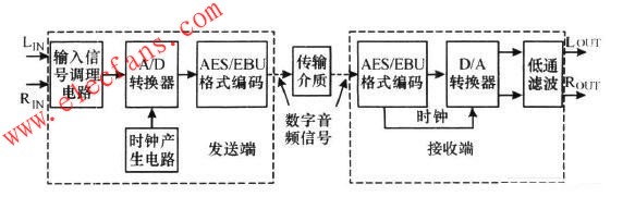
1 Introduction With the rapid development of electronic technology and digital technology, digital audio has been widely used in various application fields such as recording, broadcasting and transmission of broadcast television. In many occasions, analog audio has been unable to meet the most basic requirements of the entire sound reinforcement system. The most critical issue in the design of sound reinforcement systems for large stadiums is how to solve the long-distance high-quality transmission of weak audio signals. For large venues, the transmission distance usually reaches hundreds of meters. Using traditional analog transmission methods, it is difficult to solve the problems of signal loss and electromagnetic interference and ground interference. The performance of digital audio is far superior to analog mode, so the digitalization of broadcast and television equipment has become an inevitable trend. The advantage of using digital signals for transmission and processing is that digital signals are insensitive to interference. The signal-to-noise ratio and distortion of the entire system have nothing to do with the transmission distance. For long-distance transmission, its excellent performance index is unmatched by analog transmission. At present, both radio and TV studios are developing in the direction of digitalization. As the main functional means of digital TV production, the basic theory, interface mode, audio format and system design of digital audio have also become major topics in the field of radio and television program production. However, most of the current high-performance digital broadcasting and transmission equipment are imported equipment and are expensive. This article studies and designs a high-performance digital audio transmission system applied in this field. 2 Digital audio interface standard Currently commonly used digital audio interface standards mainly include AES / EBU (AES3-1992) interface, S / PD IF interface, MAD I interface, etc. S / PD IF is mainly used as a civilian digital audio format standard. The MAD I interface is based on a dual-channel AES / EBU interface. The AES / EBU interface standard is mainly used in the field of professional digital audio. The full name of AES / EBU is Audio Engineering Society / Eu2ropean Broadcast Union (Association of Recording Engineers / European Broadcasting System Alliance), which has become a popular standard for professional digital audio. A large number of civilian products and professional audio digital equipment such as CD players, DAT, MD machine, digital mixer, digital audio workstation, etc. all support AES / EBU. The AES / EBU standard is a digital audio transmission standard developed by AES and EBU together. It is a digital device interface protocol for transmitting and receiving digital audio signals. It specifies that audio data must be encoded with 2's complement. The transmission medium is a cable that allows serial transmission of high bandwidth capacity and parallel data bytes generated by the A / D converter. When serially transmitting 16 to 20 bit parallel bytes, the least significant bit is transmitted first. The byte clock flag must be added to indicate the beginning of each sample. The final data stream is encoded with a biphase flag code. In addition, the clock information is also included. It is embedded in the AES / EBU signal stream. AES / EBU transmits digital audio data based on a single twisted pair, using a serial bit transmission protocol to transmit data over distances of up to 100 m without equalization. It provides two channels of audio data (up to 24-bit quantization). The channels are automatically timed and self-synchronized. It also provides the transmission control method and the status information (chan2nel status bit) and some bit error detection capabilities. Its clock information is controlled by the transmission end and comes from the AES / EBU bit stream. The common physical connection media for AES / EBU are: (1) Balanced or differential connection, a three-core microphone shielded cable using XLR (XLR) connector, the parameter is impedance 110Ω, the level range is 0.2 to 5 Vpp, and the jitter is ± 20 ns. (2) Single-end unbalanced connection, using audio coaxial cable with RCA plug. (3) Optical connection, use fiber optic connector. Since the AES / EBU was revised in 1992, the standard has been widely used in the recording production, digital cinema, and broadcast and television industries. It has become the most common digital audio format, with related equipment, interfaces, cables, accessories, etc., all at low prices. 3 System circuit design 3. 1 The overall scheme of the system The entire digital audio transmission system is divided into three parts: the sending end, the receiving end and the transmission medium (cable), as shown in Figure 1. The transmission medium mainly includes twisted pair shielded cable, coaxial cable, optical fiber and wireless transmission (such as PDH or SDH digital microwave), which is selected according to the specific occasion and transmission distance. Figure 1 Block diagram of the digital audio transmission system. The sending end mainly completes the work of signal access, A / D conversion, format encoding, clock generation and so on. In order to increase the dynamic range of the signal and prevent aliasing distortion during A / D conversion, a signal conditioning circuit and anti-aliasing filter should be set in the analog input channel. The receiving end mainly completes the reception and decoding of AES / EBU format data, recovers the main clock signal and synchronization signal, and then performs D / A conversion on the audio data. 3. 2 Sending circuit design According to the system solution described in the previous section, we select CS5381 and CS8406 of Cirrus Logic Company to complete the A / D conversion of analog signals and AES / EBU format encoding and transmission respectively. The circuit principle is shown in Figure 2. Figure 2 Schematic diagram of the sending end. CS5381 is CirrusLogic's 120 dB, 192 kHz high-performance 24 bit stereo analog-to-digital conversion chip. CS5381 can work in two modes: master and slave. Mode selection can be done through pin 2 (M / S). This design works in master mode. The sampling rate of CS5381 can be controlled by the logic levels of the three pins MD IV, M0 and M1. The selection of the master clock can be based on the selected sampling frequency and the MD IV pin. The single-speed sampling rate of 48 kHz is selected in this design, and a 12.288 MHz active crystal oscillator is used as the clock source. The conversion result of CS5381 is serial data in 24-bit complement form, and the left and right channels are output alternately, which can be distinguished by LRCK high and low levels. There are two formats for output data, namely left-aligned and I2S format, the design uses I2S format. Digital audio format encoding and transmission is done by Cirrus Logic's digital audio transmitter CS8406. The CS8406 can support a 192kHz sampling rate and meet the next-generation audio format. It can receive and encode audio and digital data. After multiplexing and encoding, it is transmitted to the cable / fiber interface. The operating mode of the device is selected as the hardware mode (H / S = 1), the input data format is I2S (SFMT1 = 0, SFMT0 = 1), and the main clock frequency OMCK is selected as 256 × FS (HWCK1 = 1, HWCK0 = 1). IL2RCK, ISCLK, SD IN are left and right clock signals, serial clock signals and audio data from CS5381; TXN and TXP are serial data output terminals, and the encoded AES / EBU format data is sent through these two pins. 3. 3 Receiver circuit design For the receiver circuit, we select the digital audio receiving circuit CS8416 corresponding to CS8406 to complete the reception and decoding of AES / EBU format audio data, and use CS4397 to complete the conversion of digital audio signals to analog signals. The circuit principle is shown in Figure 3. Figure 3 Schematic diagram of the receiving end. The CS8416 is the industry's leading 192 kHz digital audio receiver with extremely low jitter performance of 200 ps. The CS8416 receives and decodes digital audio data at a sampling frequency of up to 192 kHz, and uses a very low jitter clock recovery device to generate a clear recovered clock from the incoming audio stream. An 8: 2 input multiplexer allows up to 8 digital audio input sources, and the second output of the multiplexer provides a SPD IF pass-through feature, increasing system flexibility. The CS8416 integrates automatic detection of compressed audio input streams and CD-Q subcode decoding, and allows the signal to be selectively routed to 3 general-purpose output (GPO) pins. Working in software mode, 8 digital audio signals can be simultaneously connected in CS8416. When SDOUT is connected to 47 kΩ resistor to ground, the device works in hardware mode. At this time, RXP4, RXP5, RXP6, RXP7 will work in the second Under the function, use them to set the selected RXP0, RXP1, RXP2, RXP3 as the receiving pin. In this design, the receiving end has only one combined left and right channel digital audio signal, so we choose RXP0 and RXN as the receiving pins (the corresponding settings RXP4 = 0 RXP5 = 0), other unused receiving pins are left floating; AD0 is The signal receiving confirmation pin is connected to a light-emitting diode. When the signal is not received, the light-emitting diode is on, and when the signal is received, the light-emitting diode is off. OLRCK, OSCLK, SDOUT are left and right clock signals, serial clock signals and audio data extracted from AES / EBU data. AUD IO is a non-audio data stream indication pin, and it is also the input data format selection bit SFSEL1; C (pin 19) is the channel status indication bit, and is also the input data format selection bit SFSEL0. These two pins can be grounded or connected to a high level through a 47kΩ resistor to determine the format of the output data. The connection method selected in Figure 3 is the I2S 24 bit data format. U is the user data bit, which is grounded through a 47 kΩ resistor, and the main clock frequency MRCK is selected to be restored to 256 × FS. CS4397 is a perfect high-quality 24-bit 48/96/192 kHz stereo digital-to-analog conversion chip launched by Cirrus Logic. The LRCK, SCLK, and SDATA of CS4397 in the figure are the left and right clock signals, serial clock signals, and audio data pins, which are directly connected to the corresponding pins of the digital audio receiving circuit CS8416, and are used to receive the decoded digital audio signals. Connect C / H pin to low level is the device working in hardware mode. The M4 ~ M0 pins are used to set the sampling frequency and input data format. The connection in the figure selects 48 kHz single-speed sampling frequency and I2S24bit data format input. A INL +, A INL-, A INR +, and A INR- are the output ends of the in-phase and reverse-phase signals of the left and right channels after D / A conversion, respectively, and are connected to the low-pass filter circuit composed of NE5532 to filter out High frequency components above 20 kHz. 3. 4 Transmission media As mentioned earlier, there are four main ways to transmit digital audio signals: twisted-pair shielded cable transmission, coaxial cable transmission, optical fiber transmission, and wireless transmission. The first three methods are the standard transmission methods recommended by AES / EBU. Wireless transmission can use FM or dedicated digital microwave channels, such as the PDH digital microwave E1 interface. However, due to the inconsistent transmission rate of the E1 interface and the AES / EBU standard, it is necessary to adjust the code rate of the AES / EBU digital audio signal to make it suitable for the E1 interface. At present, there is a new way of digital audio transmission, which uses audio embedding technology to transmit through the TV channel, that is, the digital audio signal is inserted into the video signal line, field synchronization pulse (line, field blanking) period and digital component video signal Simultaneous transmission. Audio embedding technology can make the audio and video signals that had to be transmitted separately merged into a video channel for transmission, thus greatly simplifying the amplification and switching of processing equipment required for the audio and video interconnection in the studio, and enabling the simultaneous transmission and playback of audio and video This is also an important application of digital audio in the field of digital television. 4 System test and conclusion Figure 4 is a physical diagram of the digital audio transmitter and receiver. The sending end and the receiving end are connected by a coaxial cable, and the entire transmission system is tested using the HP HP8903B audio tester. The main technical indicators measured are as follows: Figure 4 physical diagram of the digital audio transmitter and receiver circuit. (1) Frequency response: Unevenness within 20 ~ 20 kHz <± 0.1 dB. (2) Signal-to-noise ratio:> 90 dB in the full frequency domain,> 94 dB at 1 kHz. (3) Distortion: <0.1%. (4) Dynamic range:> 90 dB. At present, the digital audio transmission system has been used in a broadcasting station. The PDH digital microwave is connected through the E1 interface to replace the original analog audio system. The performance is stable and the effect is remarkable. The digital audio transmission system will surely be further widely used in the digital transformation of broadcast and television broadcasting equipment and related sound reinforcement systems at the city and county levels.
Kara offers a wide range of illuminated and non-illuminated Rocker Switches.Ranging from 1 to 6 poles,4VA to 30 amp,with many styles of colors and functions,especially the switches with High-Current used very widely in the welding machines. Certifications include UL, CSA, TUV, CE, and more. Kara Rocker Switches include the KR1-Series abd KR2- Series based on different size of the panel cut-out.
Rocker Switch,Waterproof Rocker Switch,Rocker Switch 3 Pin,Rocker Switch 4 Pin Ningbo Kara Electronic Co.,Ltd. , https://www.kara-switch.com