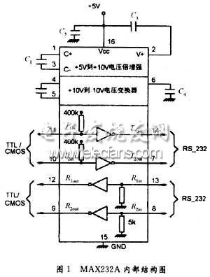
1 Introduction Computer control systems often use multi-computer systems for communication. In a distributed control system composed of a PC and a single-chip computer, the PC is often used as the upper computer to complete more complicated data processing and supervision and management of the frontier computer, as well as the lower computer. This machine introduces a PC that integrates RS232, RS485, and infrared interface-single-chip multi-function communication experiment board , which is used to realize serial communication, infrared communication and PC between PC and single-chip. Communication experiment with PC. 2 Composition principle and design of experiment board 2.1 Serial communication Serial communication refers to the transmission of data information between the sender and the receiver of the communication on a single data line, moving one binary bit at a time. His advantage is that only a pair of transmission lines is needed to transmit information, so its cost Low, suitable for long-distance communication, its shortcoming is the low transmission speed, serial communication has two basic communication methods of asynchronous traffic and synchronous communication, synchronous communication is suitable for high transmission speed, its hardware is complex, and asynchronous communication is used in The transmission speed is between 50-19200 baud, which is a more commonly used transmission method. In asynchronous communication, data is transmitted frame by frame. The data format of each serial frame consists of 1 start bit, 5-8 It consists of 4 data bits, 1 parity bit (which can be omitted) and 1 stop bit. Before serial communication, the sender and receiver must agree on the specific data format and baud rate (communication protocol) . 2.2 AT89C51 microcontroller AT89C51 microcontroller system has the advantages of simple design, reliable performance and low power consumption. It reserves enough software and hardware resources for users to redevelop and apply. In addition to the internal 4K FLASH memory, the system can also Extended location 64K ROM area and 64K RAM area for users to use, users can store their own data blocks and program segments, data tables in the form of several control subprograms and data blocks in the expansion ROM of AT89C51 microcontroller during system development Or in the RAM area, so that the system can be used repeatedly and called repeatedly. 2.3 RS232C communication interface RS232C is a voltage-type bus standard that can be used to design the connection between a computer interface and a terminal or peripheral device, with different polar voltages representing logic values. -3 ~ -25V means logic "1". + 3 ~ + 25V means logic "0". The level is different from TTL and CMOS levels, so level conversion must be performed during communication. 2.4 MAX232 chip MAXIM ’s MAX232 / MAX232A receiver / transmitter is specially designed by MAXIM to meet the EIA / TEA2232E standard. They are increasingly used in the EIA / TIA2232E standard serial communication interface. They have low power consumption and working power. It is a single power supply with an external capacitance of only 0.1μF or 1μF. It adopts a dual in-line package and the receiver output is tri-state TTL / CMOS. It is a dual-group RS 232 receiver transmitter. The working power supply is + 5V, wave High rate, only need to connect 0.1μF or 1μF capacitor, its price is low, can be used in the system that generally requires serial communication, MAX232 peripheral requires 4 electrolytic capacitors, is the internal power conversion required capacitors, their values ​​are all Tantalum capacitors should be selected for 1μF / 25V and should be as close to the chip as possible. As shown in Figure 1. 2.5 Infrared sending and receiving circuit Infrared communication uses infrared as a communication carrier to transmit data through the propagation of infrared light in the air. It is completed by an infrared transmitter and an infrared receiver. At the transmitter, the digital signal sent is properly modulated and encoded, and then sent to the electro-optical conversion The circuit is converted into infrared pulses by the infrared emission tube and transmitted into the air; at the receiving end, the infrared receiver performs photoelectric conversion on the received infrared light pulses and restores the original signal after demodulation and decoding. The infrared emitting device used in the infrared transmitting circuit is a plastic encapsulated TSAL6200 infrared emitting diode. He converts the periodic electrical signal into an infrared light signal of a certain frequency. He is an intermittent high-frequency infrared pulse signal, but the pulse train The length of time is constant, according to the size of the interval between bursts, indicating whether the data is transmitted "0" or "1". The infrared receiver performs photoelectric conversion on the received infrared light pulse, and restores the original signal after demodulation and decoding. The infrared carrier wave is a square wave with a frequency of 38KHz. It is sent by pulse width modulation PWM. The time interval between two pulse trains is controlled by the "0" or "1" of the binary data to be sent, that is, the PWM duty cycle. The infrared carrier wave can be realized by using the PWM function of the timer inside the single chip microcomputer, or can be realized by the peripheral hardware circuit. The infrared receiver uses the HS0038B infrared receiver. When receiving the 38KHz carrier signal, the HS0038B receiver will output a low level, otherwise Output high level, so that the "intermittent" infrared light signal can be demodulated into a continuous square wave signal of a certain period, and the original data signal can be recovered by the single-chip processing.
1- Output wave type: pure sine
wave, suitable for home load, perceptual negative download.
2- Inverter box: the whole shell
is made of aluminum alloy material
3- Casters: it is with casters
when inverter more than 4kw, convenient for you to move the machine
4- Display, clear LCD display,
easy to observe operating conditions.
5- Control: microcomputer (CPU)
control technology, superior performance and stability.
6- Temperature control fan: when
the box temperature reaches 35 degrees, the fan start to work automatically.
7- Protection function: built-in
loading, short circuit, under-voltage, over-pressure, over-temperature
protection function, high reliability.
8- Battery protection:
valve-Controller maintenance-free lead-acid battery, intelligent battery management,
overcharge, over-discharge protection, prolong battery life.
Off-grid Wind Solar Hybrid Inverter Off-Grid Wind Solar Hybrid Inverter,Variable Frequency Inverter,Pure Sine Wave Power Inverter,Pure Sine Wave Solar Inverter Delight Eco Energy Supplies Co., Ltd. , https://www.cndelight.com