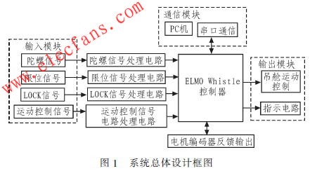
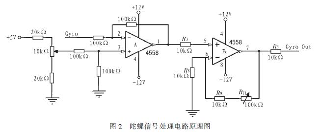
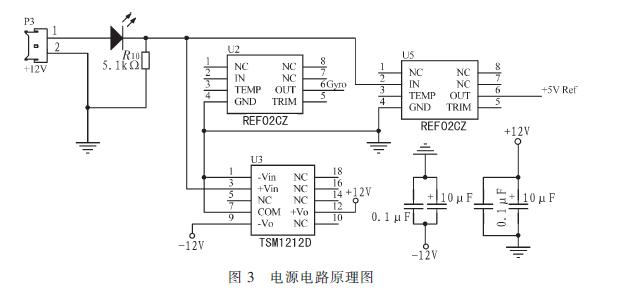
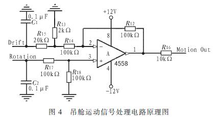
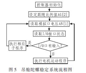
Elmo's Whistle series of digital servo controllers are small in size and light in weight, provide digital input and output interfaces, and provide two communication methods of RS232 and CAN bus, which are programmable. Using Elmo Whistle digital servo controller, through programming, only need to design a relatively simple part of the peripheral circuit, you can achieve very complex functions, reflecting the great advantages. But at present, there are few manufacturers using this controller to realize the airborne pod gyro stabilization platform, so the experience that can be used for reference is very limited. In this paper, through careful study of Elmo related documents, an airborne gyro stable platform that meets the performance indicators is designed. 1 Pod and gyro stabilization platform The gondola refers to the payload container device of the cabin suspended outside the moving carrier (such as an airplane or a ship). Its role is to isolate the impact of the carrier's attitude change and mechanical vibration on the orientation of the photoelectric sensor. The pod system consists of a gyro-stabilized platform servo platform, a TV tracking system, a cockpit display and control system, an infrared measurement system, a laser rangefinder, and GPS. 7 parts. The gyro stabilization platform system is mainly used to stabilize the visual axis of the TV and infrared cameras on the airborne pod to eliminate the interference torque caused by the sway during the helicopter flight. The platform designed here belongs to a two-axis four-frame system, which is divided into an azimuth axis and a pitch axis. A single-degree-of-freedom fiber optic gyro is installed on each axis to induce disturbance torque. The output signal of the gyro is amplified and filtered, and then sent to the Elmo servo controller, which intelligently processes the gyro signal. After the signal processing is completed, the output part of the controller drives the DC servo motor to achieve the stability of the entire system. 2 Stable platform design 2.1 Block diagram of overall system design The gyro stabilization platform designed in this article is mainly to ensure the stability of the visual axis of each light sensor. Combined with the whole pod system, it mainly realizes the following 6 functions: 1) Stability control of the current pod; 2) Realization of motion control of the pod; 3) Limit signal input; 4) Error indication circuit; 5) LOCK circuit; 6) Serial communication. Figure l is a block diagram of the overall design of the system. 2.2 Hardware circuit design 2.2.1 Gyro signal processing circuit Because the output signal of the Russian FizopTIka VG94l-3AS fiber optic gyro is very weak, the output scale factor is only 3.3 mV / deg / s. For such a weak signal, you must first process the small signal amplification circuit before it can be sent to the Elmo servo controller for the next step of processing. The point to be explained here is that the output signal of the gyro is not filtered because the Elmo servo control already has a digital filter circuit, which can be set during debugging to achieve the filtering purpose. The Elmo digital servo controller originally had two analog input ports, which can directly connect the output signal of the fiber optic gyroscope to the digital servo controller. At this time, the random output of the gyro is different. Therefore, the gyro signal processing circuit should be designed. On the one hand, the output signal of the gyro can be amplified by a certain ratio and then input into the Elmo digital servo control to reduce the scale factor in the program, thereby reducing the internal noise of the Elmo digital servo controller. The impact of the entire system, on the other hand, is achieved by compensating for the amount of drift each time it is turned on by connecting an adjustable resistor, thereby keeping the pod stable. FizopTIka VG941-3A fiber optic gyro output voltage is 2.5 V when the carrier is stationary. Therefore, to ensure that the carrier is stationary, the voltage input to the analog input port of the Elmo digital servo control is 0 V. A precision voltage chip must be used to generate a voltage of 2.5 V, and a subtraction circuit is realized through the amplifier 4558. In this subtraction circuit, a voltage of 5 V is generated with REF02CZ, and then a reference voltage of 2.5 V is obtained by resistor division. Fig. 2 is a schematic diagram of a gyro signal processing circuit (subtraction circuit). 2.2.2 Power circuit design The main purpose of the power supply circuit design here is to provide a reference voltage to each chip. TSMl212D is used to generate a ± 12 V reference power supply, which provides a reference voltage to the amplifier 4558 and REF02CZ, and REF02CZ is used to generate a +5 V reference voltage to provide a reference voltage to the amplifier. Figure 3 is a schematic diagram of the power circuit. 2.2.3 Car motion signal processing circuit In addition to the basic gyro stabilization function, the pod system must also have cruise and tracking functions. Therefore, the entire pod system also has processing circuits for rotation signals and drift signals. These two signals are controlled by the corresponding switch buttons on the control panel (HCU). Fig. 4 is a schematic diagram of the motion signal processing circuit of the pod. 2.3 System software design The software structure of Elmo Whistle digital intelligent driver can be divided into 2 parts: 1) the driver's own program, this includes the boot program, firmware and personalized settings. These programs can be downloaded through the official website, and then burned according to the specific drive model; 2) The user's own program to achieve the function designed by the user. In the system software design, the main function of gyro stability is completed. By collecting the voltage signal AN [1] fed back from the fiber optic gyro by the analog input port of the Elmo Whistle controller, the corresponding following ratio AG [2] is set in the program to realize the corresponding gyro stabilization function. The key here is the determination of the parameter AG [2]. This parameter first has an estimation process. After the estimation is completed, it can be fine-tuned in a later debugging session to finally achieve an accurate gyro stabilization function. The parameter AG [2] can be estimated as follows: 1) On the Smart Terminal interface, set the input AN [1] to 1 V, measure the speed of the pod at this time, set it to N, and check the motor speed on the Smart Terminal interface is S1, in units of count / s ; 2) The maximum induced output voltage of the fiber optic gyro is 2.5 V, and the speed of the corresponding pod should be M at this time. The value of M has been set during the design of the pod, and it is 60 (°) / s; the speed of the motor is S2 , The value of S2 is: S2 = (60 / N) xS1; 3) Scale factor AG [2] = S2 / 2.5; There are callable functions inside Elmo Whistle. Through corresponding setting statements, the controller can execute the corresponding internal functions according to the status of the six digital input ports. In this system, it is embodied as LOCK signal function, limit signal function and instruction output. Figure 5 is part of the software flow chart of the gyro stabilization system. In order to truly realize the digitization of airborne pods, in addition to the realization of the above functions, the system also made corresponding attempts to control the movement of the pods. In the original software module, a serial communication module is added by judging the state of the input port 3. If it is detected that the digital input port 3 of the controller is at a low level, the serial communication module subroutine is triggered to send a control status word to the controller to implement the command control pod function. Of course, this function can also be realized by sending corresponding instructions to the controller through the PC. 3 Conclusion Cooperating with Elmo's Studio interface and Recorder software, it can analyze whether the airborne pod gyro stable platform meets the technical requirements, and modify the system hardware circuit design and program parameters when necessary to achieve the desired goal. The airborne pod gyro stabilized platform finally designed by this system is used in the current pod system. The stability of the pod can reach 50μrad, the pitch rotation angle is -120 ° ~ + 15 °, and the azimuth rotation angle is 360 ° continuous , The maximum rotation speed is 60 (°) / s, the maximum rotation acceleration is 200 (°) / S2, and the power consumption is less than 240 W. Lithium Battery Charger can charge 3.7V LiPo battery at a rate of 500mA,1000mA, 1500mA or 2000mA per hour. It is designed to charge single-cell Li-Ion battery or battery packs Li-Polymer batteries. The charger board incorporates a charging circuit, status LED with changetable color to let you know when battery is full. Please double check the data sheet when you need to buy a battery charger . Lithium Battery Charger Lithium Battery Charger,18650 Battery Charger,Lithium Car Battery Charger,Portable Lithium Battery Charger Meile Group Limited , https://www.hkmeile.com