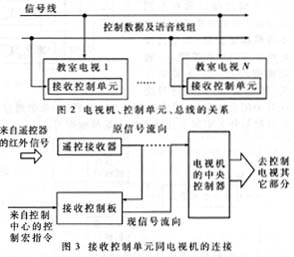
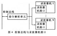
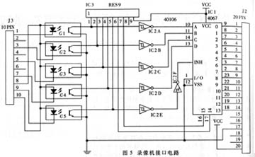
Label: Software Preparation Receive Control This article refers to the address: http:// The closed-circuit television broadcast control system of the teaching overcomes the shortcomings of such programs in the system, and the same kind of classroom programs can only be the same, so that the programs broadcasted by the classrooms have no influence on the content and time, and the classroom television can be realized. Full control of authorization. 1 system composition The whole system consists of a control center and a TV set distributed in each classroom. Each TV set is connected to the control center via a coaxial cable (program signal line) and a dedicated control bus. The connection between each TV and the control bus is equivalent to parallel connection. The receiving control unit consisting of 51 series single-chip microcomputer is embedded in the TV. This unit is mainly used to receive the macro control command of the control center and analyze it into one or several remote control commands of the TV to realize various specific control of the TV. . Each unit has its own address. The entire system can have a total of 252 addresses, that is, 252 playback devices. It is also possible to increase the number of address bits according to actual needs to increase the number of playback devices that the system can accommodate. 2 Control center composition The block diagram of the control center is shown in Figure 1. The control device consists of a PC and corresponding interfaces. The PC is used as the console, and the self-developed control software is run on it. The control macro is sent out through the serial port, and is sent to each controlled device (the playback device of the control center and the TV of the classroom) after photoelectric isolation and power amplification. The playback device is mainly composed of a video recorder, a modulator, a cable television receiving device, a mixer, a signal amplifier and the like. The audio and video signals of each video recorder are modulated and mixed with the cable signal in the mixer, and amplified by the signal amplifier and sent to the classrooms by the coaxial cable. In the frequency selection of the modulator, it should be considered in conjunction with the local cable TV program so that it does not affect each other. The possibility of expansion of local cable TV programs should also be considered. 3 receiving control unit The relationship between TV sets in each classroom is shown in Figure 2. Each TV is embedded with a receiving control unit consisting of 51 series MCUs. The relationship between this unit and the TV is shown in Figure 3. Before the control unit is disconnected, the state of the television is controlled by the remote controller. The infrared signal of the remote controller is received and demodulated by the remote receiver of the television, and then sent to the CPU of the television to implement various operations on the television. After the control unit is added, the control signal received by the remote control receiver is no longer sent directly to the CPU of the TV set, but is sent to the control unit for decoding, and the instruction control unit corresponding to the authorized function will be forwarded. Instructions that are not authorized for the function will not be forwarded. When the control center sends a control macro command through the control bus, the control unit first checks it, and then parses it and transmits it to an instruction or instruction set acceptable to the TV CPU. The control unit has the ability to simulate the remote control code, and sends the parsed command to the CPU of the television set by remote control coding to achieve the purpose of controlling the television. 4 Recording and playback camera and control bus interface In fact, the interface between the video recorder and the control bus is the control unit of the video recorder. It has no essential difference from the TV control unit, except that the encoding method of the remote controller is different. The instructions transmitted by the control center have different meanings and the interpretation of the commands is different. Since the selected video recorders are newer products, it is particularly difficult to analyze the commands of the remote controller. Therefore, the method of directly interfacing with the buttons of the recorder is adopted, that is, the commands of the control center are parsed into the buttons of the function buttons on the video recorder. move. The composition of the control unit using this method is shown in Figure 4. It consists of two parts, the left part of the dotted line is basically equivalent to the control unit of the TV set, but the receiving and decoding parts of the remote control signal are missing. In order to reduce costs, multiple video recorders can use one control unit but each output interface has a different address. The control of the recorder no longer simulates the remote control, but directly shorts the corresponding function button. The general function keys are all lock-free switches. When a key is pressed, the switch is closed correspondingly, and one end of the switch is grounded. Thus, if you want to control the switch through the interface, actually let the upper end of the switch be grounded. The actual recorder interface circuit is shown in Figure 5. IC1 (4067) is a 16-channel analog switch. When the control signal sent by J3 is sent to IC1 via optical isolation as an address, the button switch of the corresponding recorder is turned on to achieve the purpose of the button. It should be noted that some buttons cannot be pressed all the time, but they are lifted when pressed, so the corresponding switch can only be disconnected after a short time. The signal line for the button is connected by J2, which is placed in the recorder and connected to the decoding portion of the control unit via J3. The power supply +5V is provided directly by the recorder through the 20 feet of J2. 5 software preparation and communication protocol The software of this system consists of three parts: the first part is the program of TV control unit, written in C51 language; the second part is the program of recording and controlling camera unit, also written in C51 language; the third part is the console program on PC , written in VC++6.0. These three parts of the program work together to comply with the same communication protocol. The main console (PC) communicates with the TV control unit and the video recorder control unit with a small 6-byte packet. The first byte is a fixed packet start flag, the second byte is the address code, the third byte is the inverse of the address, the fourth byte is the instruction code, and the fifth byte is the instruction inversion, the last word The section is the check code. Since the first fixed byte is the start flag, the value of this byte and its inverted value can no longer be used as the address code and the instruction code. In addition, 0 and 0xFF are not used as addresses, and the total number of devices is 252 under this protocol. station. The biggest advantage of this system is that each TV does not affect the viewing time and the program, and can also authorize the remote control of the TV. Under the general right, the remote control of the TV has only the right to adjust the volume, and the program to be watched is designated by the control center. Under the authorization of the Control Center (the authorization process is also done in the console), the remote control can perform all its functions.
Antenk Standard D-Sub Series Including: Vertical Mount D-Sub Connectors wire wrap vertical board mount d-sub connectors, high profile vertical board mount d-sub connectors, low profile vertical board mount d-sub connectors, dip solder and press fit vertical board mount d-sub connectors ShenZhen Antenk Electronics Co,Ltd , https://www.antenk.com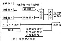
Standard Straight D-Sub Connectors Stamped Contacts
Standard High Profile D-Sub machined contacts
Standard Wire Wrap D-Sub Connectors Machined Contacts
Standard Straight D-Sub Connectors Machined Contacts
Standard Dip Solder D-Sub Connector Straight Machined Economy
Standard Density Vertical Low Profile D-Sub Connectors
Standard Density Press Fit D-Sub Connectors
Antenk's Vertical D-Sub Connectors Options
Number of Rows
Shell Size
Mounting Style
Packaging
Gender
Shell
Features of Antenk's Vertical D-Sub Standard Connectors
Available in 5 industry sizes/positions
Standard Density ( 9 pin , 15 pin , 25 pin , 37 pin, 50 pin).
Low cost & high performance, non-removable stamped contacts.
Nickel shells have indents to provide grounding and additional retention.
Optional mounting d-sub hardware available.
Materials of Antenk's Vertical D-Sub Standard Connectors
Shell: Steel, nickel plated
Insulator: Glass-filled thermoplastic. U.L. rated 94V-O
(260°C process temp)
Stamped contacts:
Male pins - Brass | Female pins - Phosphor bronze
Plating: Gold flash on entire contact
(contact factory for other plating options)
Antenk Vertical High Density D-Sub Series Including:
Dip Solder High Density D-Sub Connectors Stamped Contacts
Vertical Solder High Density D-Sub Connectors Machined
High Density D-Sub Vertical Low Profile Stamped Contacts
High Density D-Sub Vertical Low Profile Machined Contacts
High Density D-Sub Vertical High Profile Stamped Contacts
Features of Antenk's Vertical D-Sub High Density Connectors
High Profile d-subs available in Standard Density: (15 pin, 26 pin)
Stamped contacts for lower cost.
Available in receptacle (female).
Metal shell provide EMI/RFI shielding.
High profile design allows placement of other components on PCB.
Available with various hardware options.
Materials of Antenk's Vertical D-Sub High Density Connectors
Shell: Steel, nickel plated
Insulator: Thermoplastic polyester, chemical resistant, black UL 94V-O (230°C process temp)
Contacts: Female pins - Phosphor bronze
Plating: Gold flash over nickel (mating area) | Tin over nickel (solder tails)