Carbon Fiber Rigid Felt Tube,Vacuum Furnace Insulation Cylinder,Carbon Fiber Thermal Insulation Cylinder,Heat Insulation Screen Of Vacuum Furnace HuNan MTR New Material Technology Co.,Ltd , https://www.hnmtr.com
The charger is a device designed to replenish the electric bicycle battery with electrical energy. It typically consists of several key components, including a rectification and filtering circuit, a high-voltage switch, a voltage conversion stage, constant current and constant voltage control circuits, and a charging management system. The primary function of the rectification and filtering circuit is to convert the standard 220V AC power from the wall into a DC voltage of approximately 300V. This DC voltage is then processed through a high-voltage switching circuit, which transforms it into a lower DC voltage suitable for battery charging. The final charging process is managed by the charging control circuit, ensuring safe and efficient power delivery.
The charger has two main plugs: one connects to the power source (mains), while the other connects to the battery. Additionally, there are two indicator lights that display the power status and the charging progress. These visual cues help users monitor the charging process effectively.
**Ka3842_lm358 Electric Car Charger Circuit**
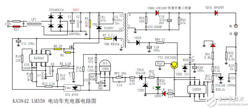
**Working Principle of Ka3842_lm358 Electric Car Charger Circuit**
The 220V AC input first passes through LF1 for bidirectional filtering. It is then rectified by VD1–VD4 into a pulsating DC voltage, which is further smoothed by C3 to produce a stable DC voltage of around 300V. This voltage is supplied to pin 7 of the pulse width modulation IC1 via a starting resistor R4. Once the voltage at pin 7 exceeds 14V, the IC1 starts operating and generates PWM pulses at its output pin 6, driving the power switch (a field-effect transistor).
VT1 operates in a switching mode, allowing current to flow through its S-D path and resistor R7 to ground. During this time, the secondary windings of the switching transformer T1 generate an induced voltage. This voltage is used to provide a stable operating voltage for pin 7 of IC1 via VD6 and R2. The oscillation frequency of IC1 is determined by the external resistor R10 and capacitor C7 connected to pin 4.
IC2 (TL431) serves as a precision reference voltage source, while IC4 (4N35 optocoupler) helps regulate the charging voltage. By adjusting RP1, a 510-ohm variable resistor, the output voltage of the charger can be fine-tuned. LED1 acts as a power indicator, lighting up red when the charger is powered on.
Once VT1 begins working, the secondary winding of the transformer outputs a rectified voltage through fast recovery diode VD60, filtered by C18 to produce a stable voltage of about 53V. This voltage is used to charge the battery via VD70, which prevents reverse current from flowing back into the charger. Another portion of the voltage is used to supply power to the LM358 comparator IC3 through R38, VZD1, and C60. VD12 provides a reference voltage for IC3, which is divided by R25, R26, and R27 and fed into pins 2 and 5 of IC3.
During normal charging, the upper end of R33 maintains a voltage of approximately 0.18–0.2V. This voltage is applied to pin 3 of IC3 through R10, causing the output at pin 1 to go high. This high-level signal is split into three parts: it turns on VT2, activates the cooling fan, illuminates the red LED in the dual-color LED (LED2), and sends a low-level signal to pin 6 of IC6, turning off the green LED in LED2. At this point, the charger enters the constant current charging phase.
When the battery voltage reaches around 44.2V, the charger transitions into the constant voltage charging stage, and the charging current gradually decreases. As the current drops to 200–300mA, the voltage across R33 decreases, causing the voltage at pin 3 of IC3 to fall below that at pin 2. This results in a low-level output from pin 1 of IC3, turning off the red LED and cutting off VT2, which stops the fan. The green LED in LED2 lights up, indicating that the battery is nearly full. However, it may still require an additional two hours for a complete charge.
At this stage, the high-level signal from pin 7 of IC3 is sent through R35 to illuminate the green LED. It also travels through R52, VD18, R40, and RP2 to the input of IC2, reducing the output voltage and entering the trickle charge mode (200–300mA). Adjusting the resistance of RP2 allows users to control the transition from constant current to trickle charging.
This detailed circuit ensures a safe, efficient, and user-friendly charging experience for electric bicycles.