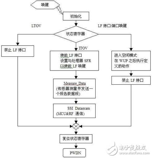
The tire pressure monitoring system (TPMS) mainly uses the pressure sensor installed in each tire to directly measure the air pressure of the tire. Through radio frequency wireless transmission, the tire pressure is automatically monitored in real time while the vehicle is running, and the tire is leaking and low. Air pressure and high air pressure alarms to ensure safe driving. Infineon's SP12/SP30 sensor for TPMS applications integrates silicon micromachined pressure and acceleration sensors, temperature sensors and a battery voltage monitor to provide four-in-one sensing with a measurement and signal Compensation and adjustment and SPI serial communication interface CMOS LSI, in which SP30 has built-in 8-bit Harvard architecture RISC MCU and 2D channel low frequency (LF) interface, and consumes only 0.4uA of current. Based on Infineon sensors SP12/SP30, Xingke Semiconductor Co., Ltd. provides ICs and solutions for the entire TPMS system to ensure system stability and reliability. TPMS composition Transmitter module The transmitter module consists of a pressure sensor, MCU, RF transmitter chip, battery and antenna. The module collects data on tire pressure, temperature, battery voltage and acceleration, and transmits the data wirelessly. The transmitter module has two schemes based on SP12/SP12T and SP30: scheme one is SP12/SP12T+MCU+TDK5100F (see Figure 1), among which pressure sensor SP12 (100~450kPa)/SP12T (0~1,400kPa) and RF The transmitter chip TDK5100F (434MHz ASK/FSK transmitter) is from Infineon. The pressure sensor SP30 (100~900kPa) has built-in 8-bit Harvard structure RISC MCU and 2D channel LF interface. The RF transmitter IC uses Infineon's TDK5100F (434MHz ASK/FSK transmitter), which can directly receive a low-frequency wake-up signal of 125kHz to control the transmitter module to operate in different modes. 2. Receiver module The receiving module consists of TDA5210, XC866/XC886, LCD module and antenna. The receiving module demodulates and decodes the information sent by the TPMS transmitting module, and outputs the received data through the LCD display. The module's MCU and RF receiver chips are based on Infineon's XC866/XC886 and TDA5210. The XC866/XC886 is an 8-bit MCU designed for automotive electronics with a CAN/LIN controller that can quickly transfer TPMS functions to secondary tasks. SP30_TPMS transmitting module principle The TPMS transmitting system is actually a timing monitoring wireless system. The core problem of the whole system design is mainly reflected in the system's low power consumption and RF receiving sensitivity and noise suppression when the car is rotating at high speed. For the Infineon SP30+TDK5100F launch system, the following is a detailed description of these two core issues. First, the system low power is built on the hardware and combined with the software program, so the choice of static low-power hardware is a prerequisite; secondly, the system should try to keep the PWDN mode with the lowest power consumption; third The hardware wake-up from the PWDN to the RUN mode should be combined with the software threshold. Finally, the system enters the RUN mode. When working in some units independent of the RISC core, the system can enter the idle mode and wait. Save on consumption. The measured quiescent current of the DEMO board is 3uA. Figure 1 shows the program flow of the SP30+TDK5100F transmission system. Figure 1: Program flow chart of SP30+TDK5100F launch system There are some things to note in the software architecture: 1. The entire software architecture consists of three modules: the initialization module, the sensor data measurement module (Measure_Data), and the RF transmission module (SSI_Datagram). These three modules are made into function packages as much as possible, which is convenient for porting and function upgrade. 2. After the interval timer (IT) wakes up the system, use the software to set several threshold areas to judge the parameter measurement and RF transmission, and save power as much as possible. For example, using acceleration measurement to determine the start/stop state of the vehicle to determine whether other parameters need to be measured, determining the approximate speed of the car to determine the RF transmission frequency, etc.; using the undervoltage and high voltage level regions to determine the RF transmission alarm frequency. These require customers to improve according to the actual situation. It should be noted that all the 阕 values ​​should not be set to a fixed value. It should be a certain area. Of course, the setting of this area should be measured repeatedly. Too small will affect the stability of the system, and it is not conducive to saving power. The measurement sensitivity is poor. 3. Use IT and LT (LF timer) to enable LF interface enable and disable LF detection, so that the LF interface can be opened normally and the host command can be detected in real time, which saves more power. Secondly, the RF receiving sensitivity and noise suppression problem when the car is rotating at a high speed. The launch module is built into the tire. In addition to the ambient temperature and RF signal shielding in the tire, it will affect the RF. What needs to be solved is the impact of the high-speed rotation of the car on the RF performance. It should be emphasized that the RF devices selected by the TPMS system are basically integrated circuits, and the performance of the RF IC directly affects the performance of the entire system. What the design engineer needs to do is to select the type of device (crystal oscillator, antenna), power amplifier and antenna parameter matching and RF layout of the IC peripheral. These aspects can basically solve the above problems. The Infineon RF TX chip TDK5100F is a low-speed (120Kbaud) low-power RF IC designed for the automotive class. The RX chip TDA5210 with its receiving sensitivity reaches -107dBm. There are some issues to be aware of in RF design: 1. The choice of crystal oscillator. The TDK5100F/TDA5210 is a narrow-band RF IC. The crystal frequency difference caused by temperature and the inconsistency of the crystal load capacitance will lead to differences in receiving sensitivity. Therefore, the selection of crystal characteristics is very important. 2. Antenna selection. The installation requirements of the TPMS transmission system are relatively high. Of course, in addition to the antenna performance, the external structure has the same high requirements. From the trade-off between the two, the spiral antenna is currently used. Although the PCB loop antenna has the best structure and cost, it needs to be corrected by the network analyzer due to its resonant center frequency and equivalent impedance, and the antenna loss caused by its own PCB material makes it not widely used in TPMS. The performance of a single-stage antenna can be done very well, but the structure does not have good mountability, and its use is not a lot. 3. TD5100F layout attention points. The crystal oscillator layout is far away from the antenna, the matching components should be placed at right angles to each other, and the antenna should not be grounded or other signal lines. 4. Under the premise that no major changes to the PCB are required, the network analyzer is used to determine the matching of the antenna parameters, and the transmission power and the receiving sensitivity are measured. Receiving module The receiving module of this system is composed of TDA5210+XC866. The actual XC866 only needs one I/O to receive the demodulated data of TDA5210. The TPMS system to be considered belongs to the automotive electronic security system. For the system task upgrade and expansion, the MCU is selected. Also trying to meet the requirements of the automotive environment, the Infineon XC866/XC886 is an 8-bit MCU designed for automotive electronics with a CAN/LIN controller that can quickly transfer TPMS functions to secondary tasks. If the TPMS function exists as a node at this time, the MCU can be released to perform other tasks. In automotive electronics, this task is quite a motor control, which uses the powerful peripheral functions of the XC866 (motor control). Unit and PWM capture comparison unit). Therefore, the choice of the receiving end MCU is not only related to the car level MCU, but also should have some advanced awareness. Summary of this article Due to the rapid growth of the automotive market, the TPMS system will have more room for development. In this market full of opportunities and facing numerous technical adjustments, choosing the right solution will enable manufacturers to succeed in this market. Very critical role. Xingke Semiconductor has introduced a reference design for TPMS that allows users to quickly bring their products to market. Brief description of the IC based on SP30_TPMS SP30: Internally integrates a low power 8 BIT Harvard architecture RISC controller; Working mode: power off, running, idle, hot shutdown; Wake-up mode: IT/LT wake-up, PORT wake-up, LF detection wake-up; Curing function library, which is convenient for users to call directly Pressure range: 100-900Kpa Temperature range: -40 to +125 ° C Voltage measurement range: 1.8-3.6V Acceleration range: -12-115g TDK5100F: 433-435MASK/FSA transmitter, PLL, VCO, power amplifier integrated inside, transmit power 5dBm, with POWER DOWN mode, CLKOUT output. Voltage range: 2.1-4V; temperature range: ? 40 ° C ~ +125 ° C; quiescent current: 0.3 nA. TDA5210: 400-440M/810-870M ASK/FSK SFR Receiver FSK sensitivity "-100dBm, ASK sensitivity" -107dBm PWDN current: 50nA Integrated LNA, PLL, VCO, MIXER, LIMITER, AGC
Stainless Steel Jar Food Blenders
Stainless steel Jar Food Blenders are better in quality and more stylish. Our Stainless steel Jar Food Blenders also can with 800ml stainless steel coffee grinders.
Discription of Stainless steel Jar Food Blenders
Size: 1.5L
Controls Type: Rotary switch
Speed: 2 speed with pulse
Power: 300/350W
Packing: 4pcs/ctn(standard box)
Stainless Steel Jar Food Blenders Stainless Steel Jar Blenders,Stainless Steel Blender,Stainless Steel Blender Jar,Steel Blender Flying Electronic Co., Ltd , https://www.flyingelectronic.com