Hp Probook 450 455 G6 G7,Hp Probook 450 G7 Keyboard,450 G6 Lcd Back Cover,450 G7 Lcd Back Cover S-yuan Electronic Technology Limited , https://www.syuanelectronic.com
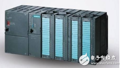
PLC (Programmable Logic Controller) is known for its versatility, ease of use, wide adaptability, high reliability, strong anti-interference capability, and simple programming. It is expected that the application of PLC control technology will become a global trend in the field of industrial automation. Today, we’ll explore common faults and maintenance techniques for industrial PLC systems.
**01 CPU Exception:**
When the CPU triggers an alarm, check all internal bus connections of the CPU unit. A practical approach is to replace each unit one by one to identify the faulty component and address it accordingly.
**02 Memory Exception:**
If memory issues occur, reprogramming may help reproduce the fault. This could be due to noise interference causing program changes, or it might require replacing the memory module if no improvement is seen.
**03 Input/Output Unit Error or Expansion Unit Failure:**
When such an error occurs, first verify the insertion status of the I/O and expansion units, as well as cable connections. Once the faulty unit is identified, replace it to resolve the issue.
**04 Program Not Executing:**
Check the process step-by-step: input → program execution → output. For input checks, use the LED indicators or a programmer’s monitor. If the LED doesn’t light up, there may be an external input problem. Use a multimeter to test voltage levels. If the LED is on but the monitor shows no signal, the issue could be with the I/O unit, CPU, or expansion unit.
For program execution, check the ladder diagram on the programmer. If the contact states don’t match the actual results, it could indicate a program error or a malfunction in the operation part.
For output checks, observe the LED indicators. If the output LED is incorrect despite correct operation, the CPU or I/O interface may be at fault. If the LED is on but no output is produced, the I/O unit or external load system could be the cause.
Note: Different PLC models may have different LED configurations, so the fault range can vary depending on the model.
**05 Some Programs Not Executed:**
This situation is similar to the previous case. However, if the input time for counters or step controllers is too short, it may result in no response. In such cases, ensure the input time is sufficient—ideally, the maximum response time of the input unit plus the scan time multiplied by two.
**06 Short Power Outage Causes Program Loss:**
Besides checking the battery, also inspect the power cycling of the PLC. The microprocessor should start correctly, and the PLC has a save program circuit during reset. If this fails, the program won't be saved. Additionally, check for noise interference from the machine system, which often causes sudden power disconnections.
**07 PROM Not Working:**
First, check if the PROM is properly inserted. If not, replace the chip if necessary.
**08 System Stops After Power-On or Reset:**
This may be due to noise interference or poor internal contact. Check for loose connections by gently tapping the PLC body. Also, verify the insertion of cables and connectors.
**09 Inverter Interference with PLC Analog Signals:**
In modern automation systems, frequency inverters are widely used, and their interference with PLC analog signals is a common issue. Here's an example of how to solve it using a signal isolation module.
**Phenomenon:**
A Siemens PLC sends a 4–20mA signal to a Siemens inverter, but the inverter fails to start.
**Fault Finding:**
1. Initially suspected the analog output board; measuring the signal showed it was normal.
2. Then checked the inverter’s input, but the problem persisted after replacing the inverter.
3. Used a hand-held signal transmitter to provide a standard 4–20mA signal, which successfully started the inverter.
4. Concluded that the inverter’s interference was affecting the analog channel.
5. Installed a signal isolation module (TA3012) between the PLC and the inverter. After installation, the inverter operated normally.
6. Confirmed that the root cause was inverter interference.
Many engineers face this issue when integrating PLCs and inverters. Based on my experience, here are some key precautions:
1. Use separate power supplies for the PLC and the inverter, and consider an isolation transformer for the PLC.
2. Keep power lines and signal lines apart, and shield signal lines to reduce interference.
3. Always use signal isolation modules for both analog input and output channels.
4. Implement software filters in the PLC program to improve signal stability.
5. Design separate grounding for signals and power to minimize noise coupling.
By following these five steps, you can effectively eliminate inverter interference with PLC analog signals and ensure reliable system performance.