Lenovo thinkpad E14,Lenovo thinkpad E14 G2,Lenovo Thinkpad E14 keyboard,Lenovo Thinkpad replacement parts S-yuan Electronic Technology Limited , https://www.syuanelectronic.com
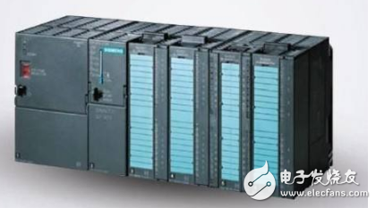
PLC is known for its strong versatility, ease of use, wide adaptability, high reliability, strong anti-interference capability, and simple programming. It is expected that the application of PLC control technology will become a global trend in the field of industrial automation. Today, we’ll explore common faults and maintenance techniques related to industrial PLCs.
**01 CPU Abnormality:**
When the CPU triggers an alarm, it’s essential to check all connections within the CPU unit to the internal bus. The best approach is to replace suspected units one by one to identify and resolve the faulty component.
**02 Memory Failure:**
If memory issues occur, reprogramming the system can help determine if the problem lies with the program. If the issue persists, it may be due to noise interference or a faulty memory chip, which should then be replaced.
**03 Input/Output Unit or Expansion Unit Error:**
When such an error occurs, first inspect the insertion status of the I/O and expansion units, as well as the cable connections. Once the faulty unit is identified, it should be replaced promptly.

**04 Program Not Executing:**
To troubleshoot, follow the input → program execution → output sequence.
(1) Check the input using LED indicators or an input monitor. If the LED is off, there may be an issue with the external input system. A multimeter can help confirm whether the input voltage is normal.
(2) Use the programmer’s monitor to verify program execution. If the ladder diagram doesn’t match the actual results, there may be a program error or a hardware fault.
(3) For output checks, observe the LED indicators. If the output is incorrect despite proper operation, the CPU or I/O interface might be at fault. If the LED is on but no output is detected, the I/O unit or external load could be the issue.
Note: Different PLC models may have varying LED connections, so the fault diagnosis based on LEDs can differ accordingly.
**05 Some Programs Not Running:**
This situation is similar to the previous one. However, if the input time for components like counters or step controllers is too short, the system may not respond properly. Ensure the input time is sufficient—ideally, the maximum response time of the input unit plus the scan time multiplied by two.
**06 Short Power Outage Causes Program Loss:**
Besides checking the battery, ensure the power supply is stable. Repeatedly turning the PLC on and off can help test the microprocessor startup. If the program still doesn’t save, there may be an issue with the memory or external circuit. Also, check for noise from the machine system, as it often causes power fluctuations during operation.
**07 PROM Not Working:**
First, check if the PROM is properly inserted. If the issue persists, the chip may need replacement.
**08 System Stops After Power-On or Reset:**
This could be due to noise interference or poor internal contact. Gently tapping the PLC body can help detect loose connections. Also, check the cables and connectors for proper insertion.
**09 Inverter Interference with PLC Analog Signals:**
In modern control systems, inverters are widely used, and their interference with analog signals has become a common issue. Here’s an example of how this was resolved:
**Phenomenon:**
A Siemens PLC’s AO point sent a 4–20mA signal to a Siemens inverter, but the inverter failed to start.
**Troubleshooting Steps:**
1. Initially suspected the analog output board, but the signal measured correctly.
2. Replaced the inverter, but the issue remained.
3. Used a handheld signal transmitter to send a standard 4–20mA signal directly to the inverter, which worked. This ruled out the output board and inverter.
4. Concluded that the inverter was causing interference.
5. Installed a signal isolation module (TA3012) between the PLC and inverter. After connecting the module, the inverter started normally.
6. Confirmed that the root cause was inverter interference on the analog channel.
Many engineers face this issue when integrating inverters with PLCs. To avoid such problems, consider the following best practices:
1. Separate the PLC power supply from the inverter’s power supply, and use an isolation transformer for the PLC.
2. Keep power lines away from signal lines, and ensure signal lines are properly shielded.
3. Always use signal isolation modules for both analog input and output channels.
4. Implement software filters in the PLC program to reduce noise.
5. Design separate grounding for signal and power systems.
By following these five steps, you can effectively prevent inverter interference with PLC analog signals.