Design of APT control system for space-based optical communication based on ARM Space optical communication is a new type of communication technology that uses light waves as a carrier to wirelessly transmit information in space. It has the advantages of high confidentiality, strong anti-interference, and high communication rate. It will be controlled from satellite to satellite, satellite and ground The station's wireless communication field plays an important role and has broad application prospects. However, due to the narrow beam of light waves and the complexity of the space environment, it has caused great difficulties in the establishment of communication links. Therefore, for space optical communication, you must first use a set of acquisition, aiming and tracking (AcquisiTIon, PoinTIng and Tracking, APT ) System to establish and maintain optical communication links. The embedded system has the advantages of high performance, low power consumption and low cost, so that it has great advantages in the application of motion control. The control system based on the ARM embedded processor has now been widely used. In view of the current satellite communication terminals must have a series of characteristics such as high real-time, high integration, low power consumption, small size and light weight, an APT control system based on ARM 7 embedded processor is proposed. 1 Composition of APT control system The APT control system consists of PWM pulse control and generation module, RS 232 serial communication interface module, photoelectric coding interface module and human-computer interaction module. The system block diagram is shown in Figure 1. The core control chip selects the special industrial control ARM chip LPC2124 produced by Philips. First receive the spot coordinate value obtained from the beacon light image processing part through the serial port, calculate the output and PWM control value through the position tracking algorithm, and then send the PWM pulse to the motor driver to drive the motor by the PWM generation module, and finally drive the turntable to point target location. The photoelectric encoder feeds back the speed information of the motor to the processor, and the corresponding control algorithm can stabilize the running speed of the turntable at the set value, preventing the motor from being disturbed due to the unstable speed. During the control process, the operating status, speed and position of the turntable can be displayed on the LCD, and the operating speed and scanning step of the turntable can be set by the keyboard. 2. 3 RS 232 interface module Obtain the coordinate value of the light spot through the serial port, because the system chip is 3.3 V system, so use MAX 3232 to carry on RS 232 level conversion, its circuit schematic diagram is shown as in Fig. 3. Set the working mode and baud rate by setting the LPC2124 control registers U0LCR, UODLM and U0DLL. 2.5 Motor control and drive design By setting the PWMMR0 and PWMMR6 registers of the LPC2124 to set the period and duty cycle of the output PWM, the running speed of the turntable is controlled. The motor drive adopts DMD402 type two-phase stepper motor driver, which can provide three operation modes: full step, half step, 8-16 gear subdivision. In addition, the orthogonal capture signal generated by the feedback of the photoelectric encoder is received through the comparison and capture unit, and the current running speed of the motor is obtained after the program processing, and then the speed is adjusted. 3 Software Design The APT control system is mainly composed of three parts: scanning, capturing and tracking. The following is an introduction to the programming of these parts. 4 Test results and conclusions After experimental testing, the maximum power consumption of the entire system is about 20 W, the rotating speed range of the turntable is 0.2 to 0.8 (°) / s, the tracking accuracy is calculated according to the standard deviation, and the minimum is about 20.69 μrad , The fastest response time can reach 200 ms. Using the ARM chip LPC2124 produced by Philips as the control core for design and development, it can be seen from the test results that the system power consumption is low, the accuracy basically meets the requirements of the APT control system, and has greater practical value.
The road lamp lighting is a main light source configuration is most widely used in Road Lighting engineering,mainly is suitable for the city roads,lans wide road lighting and decoration,is the way the functional lighting products. Our company's road lighting products include Lotus Combination Lamp,High-low arm High-power LED lamps,Lift type High-mast lamp,Integrated Solar road light.
The main road generally use high-quality steel manufacturing,stable structure and generous,illumination power and the main rod highly visible road width of scientific allocation.To ensure that the surface brightness,no glare,uniform illumination.Long distance continuous configuration,can describe the spatial light continuous beauty,make city roads at night more grandeur.
Road Lighting Series,Road Lighting,Road Lighting Decoration,Road Lighting Book Jiangsu chengxu Electric Group Co., Ltd , https://www.satislighting.com
2 Hardware design
2.1 Introduction to LPC2124 processor LPC2124 is based on a 32-bit ARM7TDMI-S CPU that supports real-time simulation and tracking. It is the world's first encryptable ARM chip with 256 KWord embedded high-speed FLASH memory and 16 KB SRAM. It can fully meet the requirements of the system storage space, so no additional storage expansion is needed, making the system simpler and more reliable. There are many application components such as UART, hardware I2C, SPI, PWM, ADC, timer and comparison capture unit, which are very powerful and can meet the functional design requirements of the APT control system. 3.3 V and 1.8 V power supply voltage can keep the system low power consumption, 128-bit width memory interface and unique acceleration structure can make 32-bit code run at the maximum clock rate, improve the code running speed, unique The 16-bit Thumb mode can reduce the code size by more than 30%, but the system performance loss is very small, which improves the efficiency of the code and greatly reduces the difficulty of optimizing the program. Especially suitable for industrial control, medical system and access control system.
2. The power supply voltage of the core and on-chip peripherals of the LPC2124 power supply circuit is 1.8 V, the required voltage of the I / O port is 3.3 V, and the power supply of the entire digital circuit is 5 V, and the power supply is 5 through 78M05. V regulated voltage, so chose LDO chip LM1117MPX-3. 3 and LM1117MPX-1. 8 regulated voltage output 3.3 V and 1.8 V voltage, its circuit is shown as in Fig. 2. 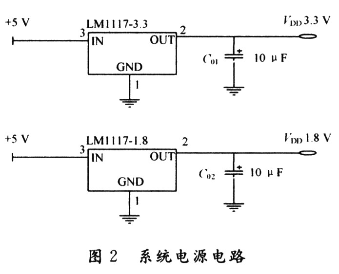

2. 4 JTAG interface circuit design uses the standard 20-pin JTAG proposed by ARM as the emulation debugging interface. The definition of JTAG signal and the connection with LPC2124 are shown in Figure 4. In the figure, the signals nRST and nTRST on the JTAG interface are connected to the reset circuit of the entire system to achieve the purpose of resetting together with the control system. 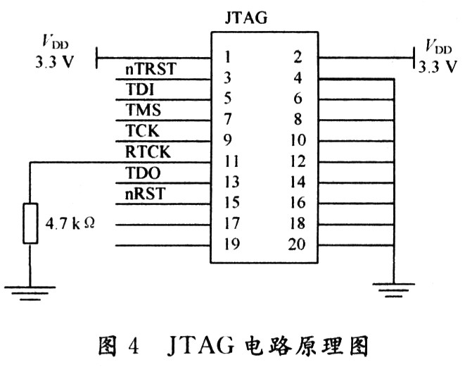
2.6 LCD display and keyboard design Use dot matrix LCD to realize Chinese prompt interface, which enhances human-computer interaction. A 128 × 64 dot matrix LCD is used in the design, and the built-in T6963C is used as a controller. In addition, a 4 × 4 matrix keyboard is used as user input.
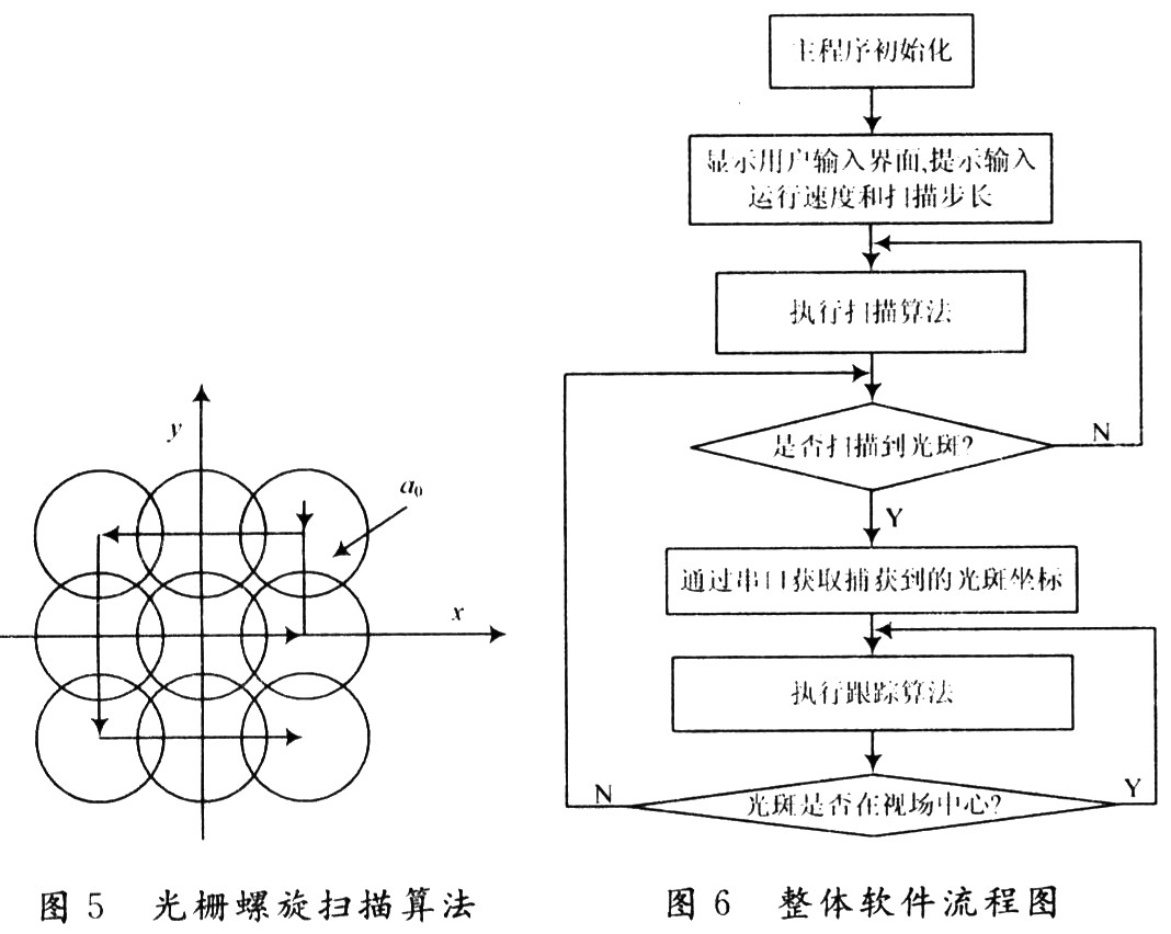
3.1 Scanning and capturing part After power-on reset operation, the program first completes the initialization work of each part, displays the welcome interface, and prompts the user to enter the running speed of the turntable and the scanning step size, and then the program starts to execute the raster spiral scanning algorithm. The schematic diagram of the raster spiral scanning algorithm is shown in FIG. 5, each small circle in the figure represents a beacon scanning sub-region, and each sub-region overlaps in a square manner. Let the diameter of each sub-area be the beacon divergence angle α, then the scan step size is: ![]()
The target is searched in the uncertain area with the step size α0 until the beacon spot is captured, and then the tracking state is entered.
3.2 Tracking algorithm based on incremental PID control PID control algorithm includes positional PID control algorithm and incremental PID control algorithm. The incremental PID control algorithm is commonly used in real-time control systems, and its formula is: 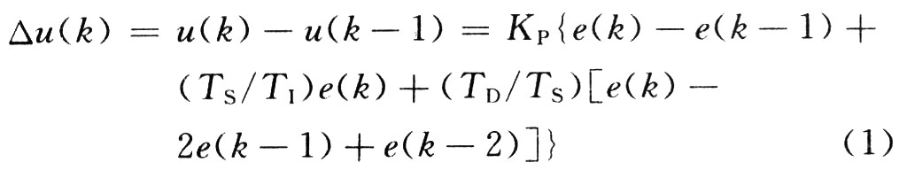
In the formula: △ u (k) is the control quantity of the output; q0 = KP; q1 = KP (TS / TI); q2 = KP (TD / TS) are the coefficients of the comparison term, integral term and difference term; Sampling time, for different control systems, TS is different, to be determined according to actual debugging experience, TS in this experiment is 0.15 s. It can be known from equation (1) that as long as the last three error sample values ​​e (k), e (k-1), e (k-2) are stored, △ u (k) can be calculated, so as to realize the position and velocity Feedback control to complete stable tracking.
3.3 System flow chart From the above analysis, the system flow chart can be obtained as shown in Figure 6.