2 System hardware circuit principle analysis and design The entire system hardware circuit is composed of comparison shaping circuit, frequency multiplier circuit, single-chip AT89C51 and display circuit. The single chip microcomputer needs to process 2 input pulses, which are the phase difference pulse and the count pulse obtained by the frequency doubling circuit. It is required to count the counting pulse when the phase difference pulse is high level, and process and display the count value by software. Therefore, the phase difference pulse can be used as the gate control pulse of the counter to input from the P3.2 / INT0 pin of the AT89C51, and the count pulse is input from the P3.4 / T0 pin. The start count of T0 is controlled by INT0. When GATE0 and TR0 are both 1, T0 is allowed to count only when the pin P3.2 / INT0 input is high. Using this function of GATE0, the external counting pulse value W of the phase difference pulse width can be easily detected. 4 Conclusion This system can measure the phase difference between two sinusoidal signals of the same frequency within a certain frequency range, and can achieve a stable measurement accuracy (0.5 °). In practical applications, the measurement accuracy can be improved by increasing the frequency-doubling coefficient of the frequency-doubling circuit. The single-chip system can use a higher crystal frequency to increase the frequency measurement range. references
Heavy Duty Connector, also known as HDC, is widely used in construction machinery, textile machinery, packaging and printing machinery, tobacco machinery, robots, rail transit, heat runner, electric power, automation and other equipment requiring electrical and signal connection. The international advanced features of Heavy Duty Connectors in structural design and material usage make the connectors outstanding in electrical performance.The reliability of the electrical connection system can not be achieved by the traditional connection method.
We developed numerous professional tools for practical use as well as provide effective guarantee for your safe and accurate installation of heavy duty connectors.
Crimp Contact,Contact Crimping Tool,Heavy Duty Connector Tool,Heavy Duty Power Connectors Suzhou WeBest Electronics Technology Co.Ltd , https://www.webestet.com
Keywords: MCU, frequency doubling circuit, phase difference
1 Introduction The purpose of this design is to measure the phase difference between any two sinusoidal signals of the same frequency and display the measurement results in digital form. The specific implementation method is as follows: first, the two channels of the same frequency signal are converted into corresponding pulse signals through a comparison circuit, and then one of the signals is inverted by the inverter and then combined with the other signal to obtain a pulse of equal pulse width Waveform, the pulse width t of this pulse waveform represents the phase difference of the two signals. After multiplying any pulse signal (period T) corresponding to the original signal as the count pulse of the single-chip counter, and counting the phase difference pulse, the value is W. Set the frequency-doubling coefficient of the frequency-doubling circuit as A, then the counting pulse period is T / A, and the formula for calculating the phase difference angle of the two signals is as follows: 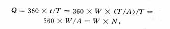
Among them N = 360 / A, N is a constant, it is the minimum accuracy of the phase measurement system.
This simple calculation formula can be realized after the single chip system programming, and the calculation result Q is sent to the LED display. The principle block diagram is shown in Figure 1. 
2.1 Comparison and shaping circuit The circuit uses voltage comparator LM339. There are 4 voltage comparators in LM339, just take two of them. The two signals are connected to the in-phase input terminals of the two comparators respectively, and the inverting input terminal is grounded to form a zero-crossing comparison circuit. The two comparator outputs are converted into pulse signals. After inverting one of the pulses through the inverter CC4069 and the other signal through the AND gate CC4081, you can get a pulse signal with the same pulse width. This pulse width records the phase difference between the two input signals. This is the phase difference pulse width. The conversion process is shown in Figure 2. 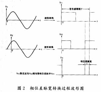
Two CC4518 dual BCD synchronous addition counters achieve frequency division by 10 and frequency division by 72, respectively. When the output signal of the frequency divider is consistent with the input signal fi of the phase-locked loop, the frequency of the output signal latched by the phase-locked loop chip is fo = Afi, thereby achieving frequency multiplication. If the input signal frequency fi = 50Hz, the output frequency fo = 36kHz. 
2. 3 single chip processing and display circuit AT89C51 single chip is used for data processing and display control of this system. The principle diagram is shown in Figure 4. 
The phase difference value can be obtained according to the calculation formula Q = W × N = 0. 5W. Send the data Q to the display circuit for display. Since the range of the phase difference Q is 0 to 180 °, considering that there may be one decimal place (w is an odd number), a 4-digit 8-segment LED digital tube is used for display. In the design, the P0 port of the AT89C51 is used as the segment selection bit of the 8-segment display, and P0.0 to P0.7 respectively correspond to the abcdefgh segment of the digital tube. The P2 port is used as the bit selection position, and P2.0 to P2.3 respectively correspond to the 4-digit digital position selection terminal from high to low, using dynamic scanning display technology. Since this kind of display circuit is relatively simple, it will not be repeated here.
When the single-chip timer / counter is used as a counter, the count pulse signal from the corresponding external input pin T0 or T1 generates a transition from 1 to 0, and the value of the counter is increased by 1. Since it is determined that the next jump takes 2 machine cycles, that is, 24 oscillator cycles, the maximum frequency of the externally input count pulse is 1/24 of the oscillator frequency. This system uses a 6MHz crystal oscillator, which can calculate the maximum frequency that the measured signal can reach is: 6000000/24/720 = 347 Hz. Therefore, the frequency range of the input signal that this system can measure is: 0 ~ 347Hz.
3 Software design The system software mainly counts the phase difference pulses, converts the value, and displays the degree value of the phase difference on the display. The system software flow diagram is shown in Figure 5. 
2 Edited by Hu Hancai. Microcontroller principle and its interface technology. Beijing: Tsinghua University Press, 1996
This paper introduces the design of the phase difference measurement of two sinusoidal signals with the same frequency using the single-chip microcomputer as the core, and the hardware and software of the system are described in detail. 2.2 The frequency doubling circuit is known from the phase difference calculation formula. The larger the frequency doubling factor A, the higher the measurement accuracy and the more accurate the measurement. This circuit uses the frequency doubling circuit of A = 720, so the phase measurement accuracy is N = 360/720 = 0.5 °, which can meet the actual needs. The frequency doubling circuit is composed of a phase-locked loop integrated circuit CC4046 and a dual BCD (Binary-Coded DecimalNotaTIon) synchronous addition counter CC4518. The circuit block diagram is shown in Figure 3. 1 Li Hua editor. MCS-51 series MCU practical interface technology. Beijing: Beijing University of Aeronautics and Astronautics Press, 1993