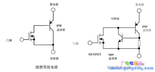
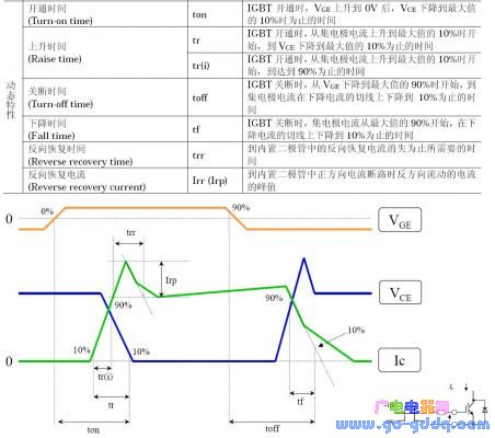
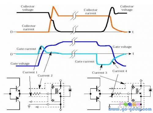
IGBT, short for Insulated Gate Bipolar Transistor, is a hybrid semiconductor device that combines the advantages of both MOSFETs (Metal-Oxide-Semiconductor Field-Effect Transistors) and bipolar junction transistors (BJTs). It features low driving power and fast switching speed from the MOSFET input stage, while offering the high current capability and low saturation voltage of a BJT in the output stage. This makes IGBTs ideal for high-power applications where efficiency and reliability are critical. The IGBT operates efficiently in the frequency range of tens of kilohertz, making it widely used in motor drives, power supplies, and industrial control systems. Its unique structure allows it to handle higher voltages and currents compared to standard MOSFETs, while maintaining relatively low switching losses. The ideal equivalent circuit and actual equivalent circuit of an IGBT are shown below: While static characteristics such as on-state voltage and current are important, the dynamic performance—especially switching characteristics—is often the main focus when analyzing IGBT behavior. These include turn-on and turn-off times, which significantly impact the overall efficiency and performance of the circuit. A detailed process of the dynamic characteristics can be seen in the following table and graph: IGBT Turn-On Process The IGBT turn-on process can be divided into several stages: In the table above, the key parameters are defined as: On time (Ton), rise time (Tr), and Tr.i. Additionally, the turn-on delay time (td.on) is calculated as td.on = Ton - Tr.i. IGBT Turn-Off Process During the turn-off process, the drain current waveform splits into two segments: The key parameters in the table are: Off time (Toff), fall time (Tf), and Tf.i. Another important parameter is trv, which represents the rise time of the DS terminal voltage, along with the turn-off delay time (td(off)). The fall time of the drain current (Tf) consists of two parts: t(f1) and t(f2). The total off time can be expressed as Toff = td(off) + trv + t(f). The sum of td(off) and trv is also referred to as the storage time. The gate current, gate voltage, CE current, and CE voltage of the IGBT are clearly illustrated in the following figure: By comparing the gate characteristics of a MOSFET and an IGBT, we gain a clearer understanding of their differences and similarities. Here's a visual comparison of their turn-on processes: Bosch Starter Motor Accessories,Bosch Starter Engine Oem,Bosch Starter Motor,Bosch Auto Starter Motor YIWU JINGHONG AUTO PARTS CO.,LTD , https://en.jhauto.ru