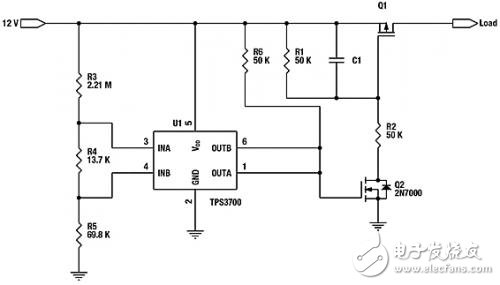
Methods for avoiding circuit system failures and managing power surge currents in electronic products have evolved from simple fuses or P-channel FETs to more advanced solutions. These highly integrated solutions not only manage surge inflows, but also ensure that the transmission components (usually FETs) are in the Safe Operating Area (SOA). This can significantly improve control and fault telemetry for system diagnostics. This article will discuss enhanced solutions for system protection and key related issues. Simple system protection The simplest form of protection for an electrical circuit is a fuse of the appropriate rating. In-depth study of the appropriate solution for your current application will reveal a variety of fuses to choose from, including but not limited to fast fuses, slow fuses, polysilicon fuses and smart fuses. There are different types of fuses because each fuse has its own advantages and disadvantages. Fast-acting wire as its name suggests: it can be blown quickly, which means that it is likely to have a false jump, resulting in product recycling. Therefore, when selecting this type of fuse, please pay attention to the rating reduction of more than 50%, that is, the fuse rating of the 5A rail should be higher than 10A to avoid application error. Slow fuses begin to blow for a longer period of time, but still exhibit false transitions, so the nominal turndown is usually at least 50%. The advantage of polysilicon fuses is that they can be recovered automatically if the fault is eliminated, but at a cost. The subsequent trip point threshold for each hop will decrease, which is easier to jump. Therefore, the probability of a false jump will increase over time. Smart fuses or three-terminal fuses are devices that can be blown on demand or blown during overcurrent. The cost of such a fuse is usually higher than the above fuse, and the power supply voltage needs to be kept at a certain height to blow the fuse. Otherwise, in the event of a fault, all components will be hot and may not be safely shut down. All four of these solutions have two major problems that can cause error hopping. First of all, they can't limit the inrush current that enters the system when power is on or after power-off. Second, because of the need to lower the rating, they may allow a large amount of current to pass in the event of a system failure, causing the faulty circuit system to overheat, resulting in more Serious failure. For example, a 12V rated 5V system may attempt to use a fuse with a current rating of 10A or higher. If a good power supply is short-circuited, the faulty circuit may have a power of up to 120W. Surge management Most error transitions are caused by inrush currents. A low-cost method to minimize inrush current may be implemented with a P-channel FET and two resistors and capacitors (Figure 1). Of course, this circuit is already in contact at the moment the input voltage appears, so it is usually necessary to keep the circuit disconnected before a good power signal is detected. Figure 2 shows a possible implementation using a window comparator that ensures that the 12VAC adapter voltage is between 10.8V and 13.2V. As long as the wide power supply voltage window comparator such as the TPS3700 finds that the adapter is in the active voltage window, the power path through Q1 can be enabled. Figure 1. Simple Surge Management Solution Figure 2. Using the TPS3700 as an AC Adapter Detector The above methods may work for some design options, but there are also some inherent problems: 1. Depending on the size of the load capacitor, both methods may affect the safe working area (SOA) of the FET; 2. Once enabled, it is not possible to limit the current entering the load; 3. If the load is shorted, the FET may fail at startup, which may occur before the fuse. It is best to use a FET that is much higher than the FET required to reduce the risk, which in turn leads to an increase in solution cost. . There must be a better way to protect the system when a system startup or system level failure occurs.
Glass-fiber covered polyester film covered rectangular copper (aluminium) wire .includings Glass-fiber Polyimide Film Covered Flat Copper Wire, Glass-fiber Polyimide Film Covered Flat Aluminium Wire, Glass-fiber Polyester Film Covered flat Copper Wire , Glass-fiber Polyester Film Covered flat Aluminium Wire, Glass-fiber Covered flat Copper wire, Glass-fiber Covered flat Aluminium wire.
Packaging of Products
30/50/150 kg wooden spool
Application: medium and large electrical motor and transformer windings
Film Covered Wire Aluminium Wire,Film Covered Wire,Polyimide Film Covered Copper Wire,Film Covered Flat Wire HENAN HUAYANG ELECTRICAL TECHNOLOGY GROUP CO.,LTD , https://www.huaonwire.com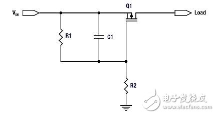
About Film Covered Wire
