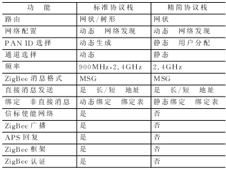
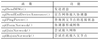
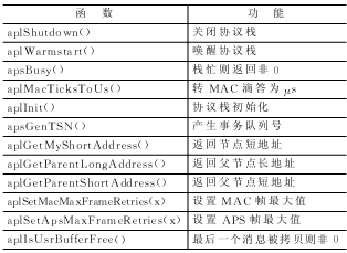
Analysis of ZigBee network nodes using reduced protocol stack ZigBee is an emerging wireless network technology with short distance, low power consumption, low data rate, low cost and low complexity. ZigBee is in the position of the network layer in the entire protocol stack, and the PHY (physical layer) and MAC (media access control layer) are implemented by the IEEE 802.15.4 specification. ZigBee can form a star, mesh, and tree network topology, which can be used for wireless sensor network (WSN) networking and other wireless applications. ZigBee works in the 2.4 GHz unlicensed band and can accommodate up to 65 000 nodes. The power consumption of these nodes is very low, and it can work for 6 ~ 24 months with only two No. 5 batteries. In addition, it also has high reliability and safety. These advantages make WSN based on ZigBee widely used in industrial control, consumer electronics, automotive automation, home and building automation, medical equipment control, etc. The ZigBee protocol is formulated by the ZigBee Alliance and is the core of ZigBee. At present, the price of a full-featured development system with a ZigBee protocol stack abroad is very high, and all ZigBee / 802.15.4 protocol stacks only provide binary / unmodifiable target code libraries for users to use. The ZigBee Lite protocol stack code studied in this paper is open and can achieve the effect of the standard version of the protocol stack in some applications, but the cost is much lower, so it has higher research value and application value. 1 Introduction to ZigBee Streamlined Protocol Stack Professor Robert Reese of Mississippi State University in the United States has developed a simplified ZigBee protocol stack for teaching and research purposes. The function pairs of the standard protocol stack and the reduced protocol stack are listed in Table 1. It can be seen that the reduced protocol stack implements the main functions of ZigBee. Some domestic research institutes have expanded this streamlined agreement to realize some functions that they did not have. Here are some additional term concepts, which helps to understand the code structure of the protocol stack. The 8-bit 802.15.4 network address of the IEEE Address node, also known as the long address. Table 1 Table 2 2 ZigBee protocol programming For practical applications, the most important is the APL function of the protocol stack. Each layer of the protocol stack has its own finite state machine (FSM) to track the operations to be performed. The top state machine function is apsFSM (). This function needs to be called at the earliest to make the protocol stack run. This is equivalent to the APLTask () function in the standard stack. All application layer functions begin with apl or aps. These functions are divided into two categories: one is the access function to the data in the stack, and the other is the service function (call) that triggers a series of events during the data transmission process. It should be noted here that service calls cannot overlap, which can be judged by calling the apsBusy () function. 2.1 Node programming If the node acts as a coordinator, then LRWPAN_COORDINATOR needs to be defined; if the node acts as a router, LRWPAN_ROUTER needs to be defined; if neither is defined, it will act as an RFD node. main () { The router node runs the protocol stack by calling aplJoinNetwork (). code show as below: main () { 2.2 Send message The application sends a message packet by calling the aplSendMSG () function. The definition of this function is as follows: aplSendMSG ( The message is sent from the source endpoint of the source node to the target endpoint of the target node. Messages are divided into direct messages (target addresses are specified) and indirect messages (only source nodes, source endpoints, and clusters are defined, and no target addresses are specified). Endpoint numbers from 1 to 255 are set by the application (endpoint 0 is reserved for use by the stack). When the message is sent, the protocol stack will route the message to the parent node. If an ack confirmation from APS is received, the protocol stack will send the message to the target endpoint. 2.3 Receive messages The protocol stack uses the following APL access functions to receive data packets. aplGetRxDstEp () returns the destination endpoint Then the user callback function usrRxPacketCallback () will be called. This function will save the data using the user data structure and set the flag bit of the received data. The pointer of the message data will be released after the end of this function, so the data should be saved before the function ends to prevent the next packet from overwriting the data. 2.4 Writing user applications When writing user applications, determine the connection method of the endpoint. A simple way is for the RFD node to return data to the coordinator node periodically. This is relatively simple because the address of the coordinator is always 0. It is difficult to use direct communication between RFD nodes. Because the short address of the RFD node is determined by the order and depth of its access to the network, it is not known in advance. Of course, a program can be added on the coordinator node to inform the RFD node of their address, but this increases the complexity. A better way is to use non-direct messaging to communicate between RFD nodes. RFD nodes send messages to the coordinator node, and the coordinator node sends data to the correct node according to the binding table. The operation of the entire program is maintained by a finite state machine. Figure 1 shows the state transition diagram of this state machine. 2.5 Function summary In view of the importance of the APL layer function interface to program design, a summary of these functions. Table 3 APL service call Table 4 APL / APS access and function functions Table 3 is the APL service, these functions need to call apsBusy () to determine whether it is completed, and use aplGetStatus () function to return the status. Table 4 is APL / APS access and function functions. Conclusion The wireless sensor network has broad application prospects. The ZigBee protocol can easily and effectively build a wireless sensor network. In the entire application, the main hardware device can be composed of a 51 single-chip microcomputer plus 2.4 GHz transceiver module. CC2430 is used for more convenient use, and the real core of ZigBee is the protocol stack code installed in the single-chip microcomputer. The simplified protocol stack has certain advantages from the development difficulty to the use cost. In this paper, a detailed analysis of the simplified protocol stack, especially the application layer interface and code implementation, is given, and based on this, the node's software and hardware design are given. Understand the use of the protocol stack, you can develop a variety of applications that meet our needs. UFO Led High Bay Light,UFO High Bay Led,UFO High Bay Light,Led UFO High Bay Light Jilin Province Wanhe light Co.,Ltd , https://www.wanhelight.com
The 2-bit network address of the Network Address node, also called short address.
PAN personal area network.
PAN ID personal area network identifier.
HAL protocol stack physical abstraction layer.
PHY protocol stack physical layer.
MAC protocol stack media access control layer.
NWK protocol stack network layer.
APS protocol stack application support layer.
APL protocol stack application layer.
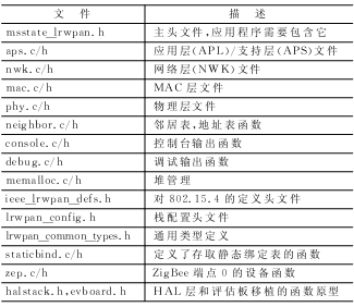
The code structure of the simplified protocol stack is listed in Table 2. 

The coordinator node forms a network, then enters an infinite loop and calls apsFSM () to run the protocol stack. After calling the aplFormNetwork () service, call the function aplGetStatus (). If LRWPAN_SUCCESS is returned, the service call was successful. code show as below:
halInit (); // Initialize HAL layer evbInit (); // Initialize evaluation board aplInit (); // Initialize protocol stack ENABLE_GLOBAL_INTERRUPT (); // Open interrupt aplFormNetwork (); // Form network while (apsBusy) ()) {apsFSM ();} // Waiting to complete while (1) {apsFSM ();} // Run the protocol stack}
halInit (); // Initialize the HAL layer evbInit (); // Initialize the evaluation board aplInit (); // Initialize the protocol stack ENABLE_GLOBAL_INTERRUPT (); // Open the interrupt to try to access the network until successful do {aplJoinNetwork (); // Connect Into the network while (apsBusy) ()) {apsFSM ();} // Wait for completion} while (aplGetStatus ()! = LRWPAN_SUCCESS);
while (1) {apsFSM ();} // Run the protocol stack
}
BYTE dstMode, // Address mode of destination address LADDR_UNION * dstADDR, // Pointer of destination address BYTE dstEP, // Target endpoint (not used in direct message mode)
BYTE cluster, // cluster number (only for direct messages)
BYTE scrEP, // message source endpoint BYTE * pload, // user data buffer pointer BYTE plen, // buffer byte number BYTE tsn, // message transaction queue number BYTE reqack // confirm if non-zero)
aplGetRxCluster () returns the cluster number
aplGetRxSrcEp () returns the source endpoint
aplGetRxSADDR () returns the short address of the source endpoint
aplGetRxMsgLen () returns the message length
aplGetRxMsgData () returns a pointer to the message data
aplGetRxRSSI () returns the signal strength of the received message 
Figure 1 State transition diagram of finite state machine 
