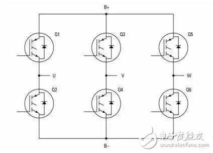
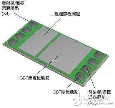
Hybrid electric vehicles (HEVs) and electric vehicles (EVs) are gradually being accepted by the market, which has created many business opportunities for the electronics industry. Although the proportion of electronic components in the typical automobile bill of materials has gradually increased in recent years, the use of electric traction is expected to become a major advancement in shaping modern automobiles into electrical installations. As part of the high-voltage infrastructure of hybrid electric or pure electric vehicles, the IGBT converter power module is a key component for controlling the drive train in the traction motor. The typical module consists of a three-phase full-bridge converter consisting of six IGBT switches and several freewheeling diodes, as shown in Figure 1. Several IGBT components can be used at each switch position to achieve the desired current rating and on-resistance. Figure 1: Three-phase converter for a typical HEV/EV power module. If the motor is rated at 100Kw (equivalent to 134 hp), modules with up to 97% efficiency will dissipate about 3 kW of energy in the form of heat. If the module is to provide satisfactory reliability, then effectively removing this heat is a key. Modern internal combustion engine vehicles have established high reliability standards, and electric vehicles must meet these standards to be acceptable to consumers. Improve module reliability Measures to improve module reliability and power rating include the use of chip IGBTs and optimized module structures to minimize parasitic losses that cause Joule heating and achieve the lowest thermal resistance between the IGBT wafer and the module substrate. Compared to the power modules used in the first generation of hybrid electric vehicles, the typical thermal stacking of today's modules is greatly simplified, thus minimizing the thermal resistance between the wafer and the module substrate. The substrate may have a large number of fins to achieve air cooling, or more commonly a liquid/glycol mixture for liquid cooling. The thermal superposition and electrical contacts of a typical modern IGBT power module are shown in Figure 2. Figure 2: Construction of a typical IGBT power module. As for IGBTs, it is suitable for components requiring up to 300A (or higher) current handling capability in modern high power applications. This results in wafer sizes as large as 100 mm2 (or higher). In addition, the latest generation of components are fabricated using ultra-thin wafer technology with a wafer thickness of 100um (or lower), which minimizes circuit path length, further improving turn-on performance and reducing current load. Helps improve switching efficiency. At the same time, ultra-thin wafer technology also enhances heat dissipation. However, ultra-thin wafers pose a daunting production challenge for module manufacturers, which may ultimately result in lower yields. Modules typically use IGBT die attach, which offsets the no-wafer package resistance (DFPR) and package thermal resistance (RTHj-c) associated with any secondary package, resulting in improved energy efficiency and thermal performance. Large ultra-thin wafers may break when ejected via load current or during subsequent processing. Although special processing equipment must sometimes be used, when the module is exposed to thermal cycling, larger wafer sizes may directly affect reliability. Larger wafer sizes can result in severe CTE misalignment between the wafer and the module substrate, resulting in greater stress on the soldered die connector or wafer. After multiple thermal cycles, the die connector gradually degrades, resulting in an increase in thermal resistance between the IGBT wafer and the substrate. This can cause overheating, which can degrade performance and ultimately lead to premature module damage. Manufacturers can reduce the impact of CTE mismatch between materials on the structure by soldering the wafer to a direct bonded copper (DBC) substrate. This type of assembly uses an aluminum bond wire (see Figure 2) to connect the IGBT emitter to the module terminal, typically using several thick wires between 0.25 mm (0.01 in) and 0.5 mm (0.02 in). . Reliability tests have shown that the interface between the wire and the deposited metal is prone to fatigue, thus limiting the life of the module. At the end of the test, module manufacturers encountered another challenge - production yield. They are often unable to test power semiconductor chips at full operating current before packaging. As a result, certain chip-related failure scenarios may only be discovered during the final test of the assembled module, thus reducing yield.
B&R Power Panel PP35 touch screen panel
Power Panel PP45 touch screen panel for B&R HMI repair
B&R Automation Power Panel PP65 touch panel screen
Power Panel PP100 HMI touch panel screen
Power Panel PP200 touch screen glass for BR automation repair
touch screen for Power Panel PP300 touch panel repair
B&R automation Panel PP400 touch screen panel
Power Panel PP400 embedded touch screen membrane
touch panel for Power Panel C70 touch screen repair
Keyboard membrane for Power Panel PP100 repair
Power Panel PP200 membrane keypad repair
membrane keyboard for Power Panel PP300 repair
B&R automation Panel PP400 membrane keyboard
Power Panel PP400 embedded membrane keypad repair
keypad for Power Panel C70 membrane switch repair
BR PP15 membrane keyboard switch keypad.
PHARMA FLEX touch screen panel glass repair
METTLER TOLEDO touch screen panel repair
GARVENS HMI touch screen panel glass
HMI Touch Glass,HMI Touch Screen,HMI Touch Panel,HMI Display Touch Screen GUANGZHOU VICPAS TOUCH TECHNOLOGY CO.,LTD , https://www.touchsuppliers.com