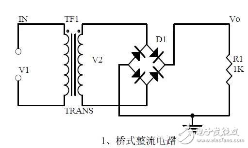
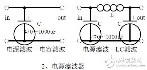
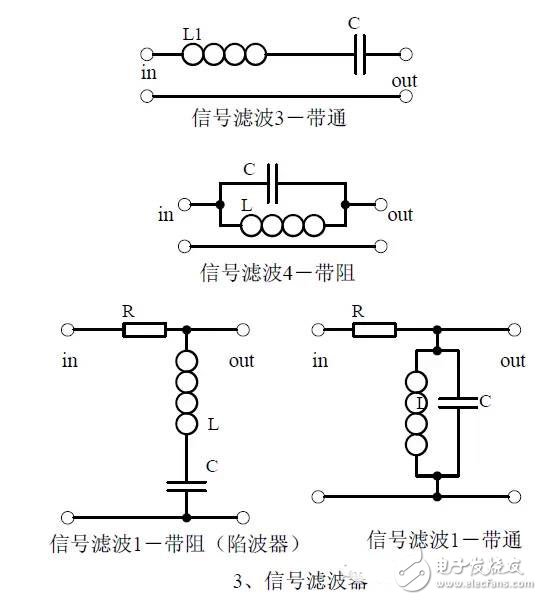
The mastery of analog circuits is divided into three levels. The primary level is to skillfully remember these twenty circuits and to understand the role of these twenty circuits. As long as it is an electronic enthusiast, as long as people who are learning automation, electronics and other electronic control professionals should be able to remember these twenty basic analog circuits. The intermediate level is capable of analyzing the functions of the key components in the twenty circuits. What is the influence of the function of the circuit when each component fails, the variation of the parameters during measurement, and the handling of the faulty components; qualitative analysis The flow direction and phase change of the circuit signal; qualitatively analyze the change process of the signal waveform; qualitatively understand the magnitude of the input and output impedance of the circuit, and the relationship between the signal and the impedance. With this circuit knowledge, you are very likely to grow into an excellent service technician for electronics and industrial control equipment. The advanced level is to quantitatively calculate the input and output impedance of the twenty circuits, the ratio of the output signal to the input signal, the relationship between the signal current or voltage in the circuit and the circuit parameters, the amplitude and frequency relationship of the signal in the circuit, and the phase-frequency relationship. Characteristics, selection of component parameters in the circuit, etc. After reaching the advanced level, as long as you are willing, a respected high-paying career - the development and design engineer of electronic products and industrial control equipment will be your preferred career. First, the bridge rectifier circuit 1. Unidirectional conductivity of the diode: Voltammetric characteristic curve: Ideal switch model and constant voltage drop model: 2. Bridge rectifier current flow process: Input and output waveforms: 3. Calculation: Vo, Io, diode reverse voltage. Second, the power filter 1. Process analysis of power supply filtering: Waveform formation process: 2. Calculation: The capacity and withstand voltage of the filter capacitor are selected. Third, the signal filter 1, the role of the signal filter: the difference and the same point with the power filter: 2. Impedance calculation, amplitude-frequency relationship and phase-frequency relationship curve of LC series and parallel circuits. 3. Draw a passband curve. Calculate the resonant frequency. Fourth, the differential and integral circuit 1, the role of the circuit, and the difference between the filter and the same point. 2. Analysis of the voltage change process of the differential and integral circuits, and draw a waveform diagram of the voltage change. 3. Calculation: time constant, voltage change equation, selection of resistance and capacitance parameters. Five, common emitter amplification circuit 1. The structure of the triode, the current relationship of the poles of the triode, the characteristic curve, and the amplification condition. 2, the role of components, the use of the circuit, voltage amplification, input and output signal voltage phase relationship, AC and DC equivalent circuit diagram. 3. Calculation of static working point and calculation of voltage amplification factor.
poe splitter 48VDC to 12VDC splitter with A&B standard
Features:
AC input:33-57V DC
Compatible with IEEE 802.3af Power over Ethernet
Data&Power In:RJ45 Connector
Data Out:RJ45 Connector
DC Out:DC male connector 2.1*5.5
Cat5 ethernet cable for data transfer
LED display for Data&Power In
Convert PoE to DC power,used for Analog Cameras,
Access Point etc.devices without PoE
Product application:
Application to AP,IP Camera,IP phone,etc
POE Splitter Adapter Injector,Single Port Poe Splitter,Security Single Port ,5V Micro Usb Poe Guangdong Steady Technology Co.LTD , https://www.steadysmps.com