This article presents the design concept of an ultra-wideband EMI filter capable of operating at frequencies up to 40 GHz or higher. At lower frequencies, the filter employs the LC reflection principle, while at higher frequencies, it utilizes a high-performance absorbing material to achieve signal absorption. This hybrid approach ensures optimal performance across a wide frequency range. By incorporating absorbing materials, the filter maintains an insertion loss of over 100 dB for frequencies above 10 GHz. This effectively addresses the limitations of traditional LC filters at high frequencies, where parasitic effects such as distributed inductance and capacitance can severely degrade performance, leading to reduced or even complete failure of the filtering function. 1. Introduction Over the past decade, shielding rooms have become essential components in microwave experimental facilities. Their application frequency ranges have expanded significantly, with high-frequency capabilities increasing from 1 GHz to 18 GHz, and even reaching 40 GHz. Looking ahead, it is expected that future systems will operate at 60 GHz or even 100 GHz. To maintain effective electromagnetic shielding across these extended frequency bands, it's crucial that both power and signal filters meet strict insertion loss specifications. This ensures that no external interference enters or exits the shielded environment through cables or lines. The ultra-wideband EMI filter described in this paper uses dielectric or magnetic media with high electrical or magnetic losses to convert high-frequency interference signals into heat, thus achieving effective filtering. These materials exhibit minimal absorption at low frequencies, ensuring that useful signals are not significantly attenuated. 2. Design Ideas for Ultra-Wideband EMI Filters The ultra-wideband EMI filter combines an LC reflection filter at the low-frequency end with an absorption filter using advanced absorbing materials at the high-frequency end. During the design process, the low-frequency section is modeled based on the user’s requirements, including passband cutoff frequency, stopband insertion loss, rated current, and leakage current. This allows the determination of necessary inductance and capacitance values, which are then used to create the corresponding circuit diagram. The low-frequency portion of the filter is typically effective up to 100 MHz. Beyond that, the performance of LC filters may degrade due to distributed inductance and capacitance in the circuit. To address this, the high-frequency section uses a hollow coaxial line filled with high-loss absorbing materials. This setup helps to attenuate high-frequency interference along the propagation path. However, care must be taken to avoid short-circuiting between the inner and outer conductors, often requiring an insulating layer. While LC filters perform well below 100 MHz, their lumped parameters become less effective at higher frequencies. In contrast, the coaxial line filled with absorbing material demonstrates excellent insertion loss characteristics at high frequencies. For applications requiring EMI suppression from 10 kHz up to 40 GHz, combining both types of filters in series provides an effective solution, forming a comprehensive ultra-wideband EMI filter design. 3. Application Examples of Ultra-Wideband EMI Filter Design Let’s consider a power filter example. Suppose the technical requirements specify a passband cutoff frequency of 1 kHz, a stopband start frequency of 10 kHz, a passband attenuation of less than 3 dB, a stopband attenuation of more than 100 dB, and an upper frequency limit of 40 GHz. The low-frequency section is designed using a Chebyshev approximation, known for its equal ripple characteristics in the passband. It offers faster roll-off in the transition band compared to a Butterworth filter, and a monotonic increase in stopband attenuation. Based on the given requirements, a fifth-order Chebyshev filter is suitable. The configuration can be either T-type or π-type. While the T-type requires more inductors, the π-type is more commonly used in practice due to its compact size and ease of implementation. In the circuit diagram, C1 = 6.4 μF, L2 = 3.5 mH, C3 = 8.4 μF, L4 = 3.5 mH, and C5 = 6.4 μF. Assuming a load resistance of 50Ω at both input and output, the Laplace transform of the circuit can be used to determine the frequency response of the low-frequency LC filter. The resulting insertion loss shows a ripple in the passband (not exceeding 3 dB), a rapid rise in the transition band (from 3 dB to 100 dB), and a monotonic increase in the stopband, confirming the effectiveness of the design.
Suzhou Whaylan new energy technology co., Ltd. is located in Suzhou Wuzhong Economic Development zone. It is a new energy conversion electric power equipment, energy storage transformation, energy management, on the basis of independent research and development, production, sales and after-sales service in the integration of high-tech enterprises, business scope covers from grid photovoltaic inverter, energy storage system, off-grid power generation systems and other fields.
Since its establishment, the company has always adhered to the original intention of "let the whole world use clean energy", deeply plough into the field of power, electronic and electric energy transformation, and is committed to providing smart energy management and other overall solutions for families, industrial and commercial users and ground power stations with innovative technology, excellent products and professional services.
Power Bank,Pd Powerbank,Phone Powerbank,Rechargeable Power Station suzhou whaylan new energy technology co., ltd , https://www.xinlingvideo.com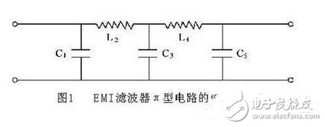

Whaylan always adhere to the concept of "innovation drives development, science and technology leads the future", product research and development is quality-oriented, efficient-based, safety-oriented as the principle, the establishment of a strong, experienced R & D team, the company has been rated as science and technology small and medium-sized enterprises, specialized new enterprises, high-tech enterprises.