Female Header section Female Header section HuiZhou Antenk Electronics Co., LTD , https://www.atkconn.com
The inverter is a device that converts direct current (DC) power, such as from a battery, into alternating current (AC), typically 220V at 50Hz with a sine wave output. It consists of three main components: an inverter bridge, control logic, and filter circuits. These parts work together to ensure stable and efficient power conversion.
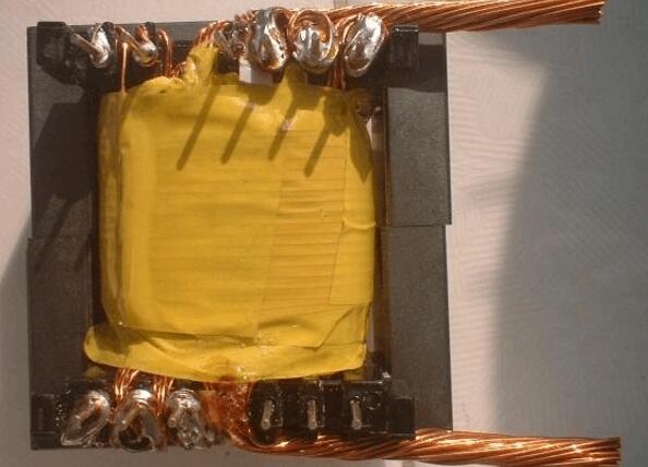
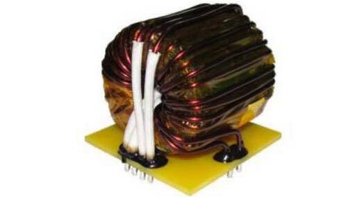
**Inverter Transformer Structural Characteristics**
1. The coil is made using F-grade or C-grade enamel wire, wound in a multi-layered cake style. This design ensures even and tight winding, without an outer insulation layer, resulting in a clean appearance and excellent heat dissipation properties.
2. The core joints are joined using sub-arc welding. After the coil and core are assembled, a process of pre-baking, vacuum impregnation, and hot curing ensures a strong bond between the coil and core. This not only minimizes operational noise but also provides high thermal resistance.
3. Exposed parts of the transformer are treated with anti-corrosion coatings, while terminals are connected using terminal blocks or copper-plated connectors for reliable electrical contact.
**Inverter Transformer Working Principle**
The working principle of the inverter involves several key stages. The control circuit manages the overall system operation, while the inverter circuit performs the DC-to-AC conversion. The filter circuit removes unwanted signals, ensuring a clean output waveform.
The inverter process can be broken down into three steps: first, an oscillating circuit converts DC into AC; second, the coil boosts this irregular AC into a square wave; finally, rectification transforms the square wave into a sinusoidal AC waveform.
The inverter described here mainly uses MOSFETs and a standard power transformer. Its output power depends on the power rating of the MOSFET and the transformer. This design eliminates the need for complex winding processes, making it ideal for hobbyists and DIY enthusiasts.
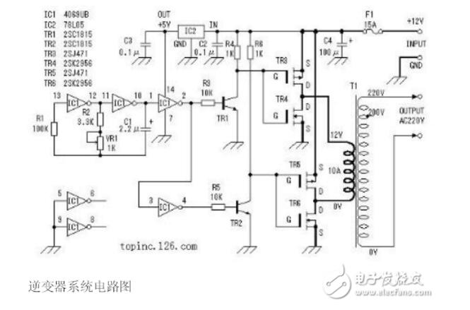
To better understand how this inverter works, let's take a closer look.
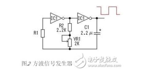
In this circuit, a six-inverter CD4069 is used to generate a square wave signal. R1 acts as a compensation resistor to stabilize the oscillation frequency when the power supply voltage fluctuates. The oscillation is achieved by charging and discharging capacitor C1. The oscillation frequency is calculated as f = 1/(2.2RC). The maximum frequency in this circuit is approximately 62.6Hz, and the minimum is around 48Hz. Actual values may vary slightly due to component tolerances.
For other unused inverters, their inputs are grounded to prevent interference with other parts of the circuit.
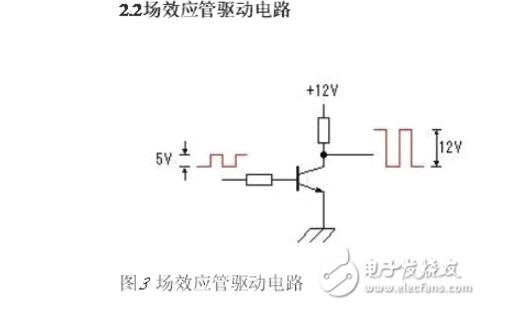
Since the square wave generator outputs a voltage ranging from 0–5V, it needs to be amplified to 0–12V to properly drive the power switch circuit. This amplification is done using transistors TR1 and TR2, as shown in Figure 3.
**High-Power Inverter Transformer Winding Method and Process**
1. Start by selecting two strands of 0.72mm enameled wire. Fix one end at the head of the high-voltage winding and wrap two layers of 35 turns. Leave the other end uncut, cover it with insulation, and begin wrapping the primary winding.
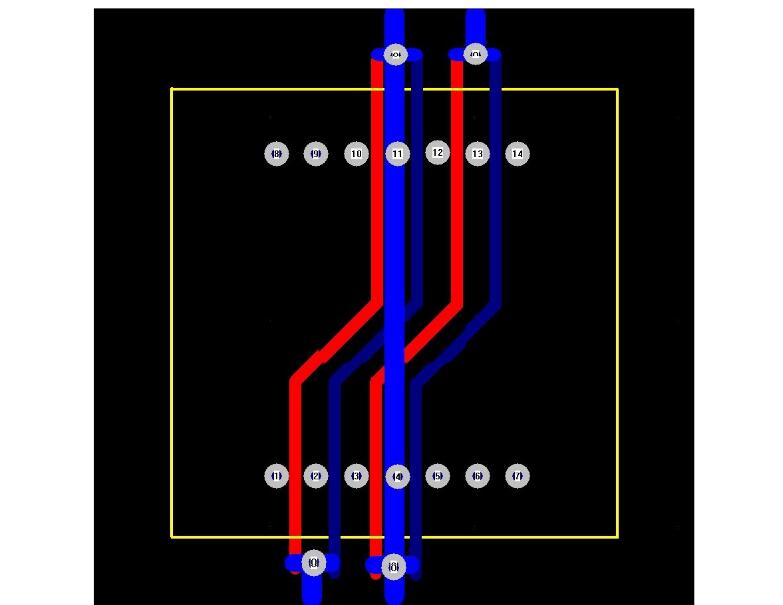
2. Choose six strands of 0.72mm enameled wire and neatly wrap them between the 1st and 2nd feet of the core. Repeat this between the 3rd and 4th feet. This creates 12 evenly spaced wires in one layer, covering 3 turns.
3. Pull out the 1st and 2nd feet wires between the 9th and 10th feet, cutting them to the appropriate length. Similarly, draw the 3rd and 4th feet wires between the 12th and 13th feet, leaving enough length for connection.
4. Repeat the same process for the pairs (2,3)-(11,12) and (4,5)-(13,14).
5. Wrap insulation and continue with two more layers of 35-turn high-voltage winding. Do not cut the end of the wire.
6. After wrapping the insulation, repeat step 2 and wind the secondary side. Ensure the end of the wire is positioned consistently.
7. Add another layer of insulation and continue connecting the high-voltage winding for a total of 7 turns.
Once all windings are completed, the entire coil package will have about 10 layers, with a thickness slightly over 7.2mm. The EE55 core skeleton is generally around 9mm, so it fits perfectly.
Finally, arrange all wire ends on the tin plate. The lines between the 1st, 2nd, and 3rd feet form a set of 3-turn heads, while those between the 12th, 13th, and 14th feet form another set of 3-turn tails. The lines between the 3rd–4th–5th and 10th–11th–12th feet serve as center taps for the two 3-turn groups.
When drawing the PCB, make sure to leave longer leads for the center taps to allow for easy connection during assembly. In actual use, these wires should be long enough to pass through a sleeve and connect directly to the power supply’s positive terminal.
One additional tip: When choosing the wire diameter, you can use the available enameled wire. However, try to calculate the number of parallel strands so that each layer fills the core window completely. With careful planning, you can achieve up to 800W of output power.