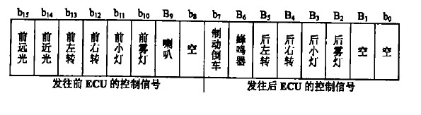
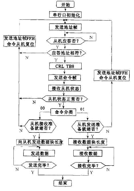
Abstract: The control signals of traditional automotive lighting and signal control systems are transmitted through dedicated wiring harnesses and do not have self-diagnostic functions. When an important control signal fails, the driver is difficult to detect and is prone to a car accident. Aiming at the above problems, a new automotive lighting and signal control system based on optical fiber communication is proposed. The control function, self-diagnosis function, hardware design and software development are introduced. Automotive lighting and signal control systems are responsible for the lighting of vehicles, signal lights, and control tasks such as electric horns, reversing and brake buzzers. Traditional automotive lighting and signal control systems are controlled by switches, relays, and dedicated electronic oscillators. The control signals are transmitted through dedicated harnesses and do not have self-diagnostics. During the driving process of the car, when important control signals such as turn signals are faulty, the driver is difficult to detect and is likely to cause a car accident [1]. 1 system hardware platform and working principle The system consists of a multi-machine system consisting of three single-chip microcomputers to realize the control of automobile lighting and signals. The system main electronic control unit ECU (Elec2tronic Control Unit) centrally encodes all input control signals and sends them serially to the front ECU (mounted on the front of the car) and the rear ECU (mounted on the rear of the car) via fiber optics. The parallel output port of the ECU outputs control signals through the opto-isolator, and controls the lighting and signal appliances at the front (tail) of the car, and monitors the front (tail) lights and signal devices of the car in real time. In the event of a fault, the front (rear) ECU immediately transmits the fault code back to the main ECU, and the main ECU alerts and displays the fault code. The system hardware platform is shown in Figure 1. Figure 1 system hardware platform 1. 1 ECU The system main ECU adopts AT89C51, the front ECU and the rear ECU adopt AT89C2051.AT89C51 built-in 4KB programmable Flash E2PROM, 128 bytes of RAM, 2 16-bit timer/counter, 1 serial communication port, 6 interrupt sources, 32 I / O lead, 3-level program memory is confidential, static operating frequency is 24 MHz. AT89C2051 built-in 2KB programmable Flash E2PROM, 128 bytes of RAM, 2 16-bit timer / counter, 1 on-chip analog comparator, 1 serial Communication port, 6 interrupt sources, 15 I/O leads, two levels of program memory are kept secret, and the static operating frequency is 24 MHz. 1. 2 fiber optic transmitter / receiver The fiber optic transmitter/receiver uses HFBR21414/ 2416. HFBR21414/ 2416 emits light at 820 nm, with a maximum data transmission rate of 155 MBd, a maximum transmission distance of 4 km, and an operating temperature range of -40 °C to +85 °C, which is suitable for 50/125 μm. 62. 5/ 125μm, 200μm HCS fiber and four connectors ST, SC, SMA and FC. The HFBR21414 fiber optic transmitter contains an efficient optical power-excited aluminum arsenic light emitter that can deliver optical power (12 dBm) at 820 nm to the fiber at 60 mA DC current. HFBR22416 fiber The receiver consists of a high-efficiency HN photodiode and a low-noise transimpedance preamplifier circuit. The optical signal is converted into an analog electrical signal by a photodiode. After amplification, it is buffered by the emitter outputter with a maximum dynamic range of 23 dB. From DC to 125 MHz. 1. 3 Working principle The main ECU encodes and stores all input control signals using two control words. The two control words are stored in the same format, as shown in Figure 2. Figure 2 Control signal storage format The main ECU T0 is timed 1.5 ms interrupted, and a square wave signal with a period of 3 ms is generated to control the car horn. With the T0 interrupt, the soft count is 250 times to generate a periodic square wave signal that causes the turn signal to flash 80 times per minute. When the input switch signal changes, or the timing time expires, or the soft count count arrives, the corresponding bit of the first control word is set, or the bit is negated. The main ECU timing 1. 5ms compares the two control words. When the two control words are different, the main ECU sends an update signal through the serial port and updates the second control word with the first control word. The front (rear) ECU receives the control signal from the main ECU and immediately compares it with the existing control signal. If it is different, the output control signal is updated. 1. 4 self-diagnosis P1. 7, P3. 2~P3. 5, P3. 7 of the front (rear) ECU are fault monitoring ports, and input self-diagnosis signals of front and rear illumination and signal appliances. Each time the front (rear) ECU sends a control signal, it receives a corresponding feedback signal at its fault monitoring port. Comparing the two signals, if they are not the same, it indicates that the lighting and signal appliances of the corresponding port have failed, and the front (rear) ECU immediately sends a fault code to the main ECU. After receiving the fault code, the main ECU will alarm and display the fault code. 2 system software The system software consists of an initialization program of each ECU, each ECU control subroutine, a self-diagnosis subroutine, and a communication subroutine. The communication between the main ECU and the front (rear) ECU uses the serial port built into the microcontroller to transmit control signals over the fiber. The main ECU and the front (rear) ECU use the communication method of inquiry and interruption respectively. The system distinguishes whether an address frame or a data frame is sent by assigning 1 or 0 to TB8 of the SCON (serial control register). The main ECU first issues an address frame and the ECU is returned to the local address. After judging that the addresses match, the main ECU issues a control command, and the ECU is returned to the main ECU to return its own state. If the ECU is found to be in a normal state, the main ECU starts transmitting or receiving data. The communication subroutine flow of the main ECU and the front (rear) ECU is shown in Figure 3. Figure 3 communication subroutine flow 3 Conclusion The novelty of the system is that it uses a 3-chip microcontroller to transmit coded control signals over fiber optics and has a self-diagnostic function. The use of optical fiber to replace the traditional wire harness has low cost, strong anti-interference ability and good control effect. [1]. SMA datasheet http://+_1054310.html.
Various products of Cob Track Lights, providing product images and basic parameters with each COB Track Lights and COB Track Lights; We are a professional Chinese manufacturer of COB Track Lights, and look forward to your cooperation!
LED Track Lights Advantages: Cost-sffective, can reach to 70lm/WAttractive appearance, strong metal feeling Good thermal conductivity, low temperature,good performance.
Led Track Lights,Cob Track Lights,20W Led Track Lights SHENZHEN KEHEI LIGHTING TECHNOLOGY CO.LTD , https://www.keheiled.com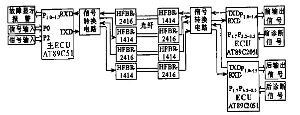
references:
0 times
Window._bd_share_config = { "common": { "bdSnsKey": {}, "bdText": "", "bdMini": "2", "bdMiniList": false, "bdPic": "", "bdStyle": " 0", "bdSize": "24" }, "share": {}, "image": { "viewList": ["qzone", "tsina", "tqq", "renren", "weixin"], "viewText": "Share to:", "viewSize": "16" }, "selectShare": { "bdContainerClass": null, "bdSelectMiniList": ["qzone", "tsina", "tqq", "renren" , "weixin"] } }; with (document) 0[(getElementsByTagName('head')[0] || body).appendChild(createElement('script')).src = 'http://bdimg.share. Baidu.com/static/api/js/share.js?v=89860593.js?cdnversion=' + ~(-new Date() / 36e5)];