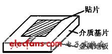
In recent years, people have begun to develop and apply contactless IC cards to gradually replace contact IC cards. Radio frequency identification (RFID, radio frequency idenTIficaTIon) card is a typical non-contact IC card. However, RFID is used in different application environments. Need to use different antenna communication technology to achieve data exchange. Since the advent of the first IC card in 1970, IC cards have become one of the fastest growing products in the microelectronics market at the time. By 1996, there were more than 700 million IC cards sold worldwide. However, this type of contact is used. The IC card has its own inevitable shortcomings, that is, the contact point is not resistant to corrosion and pollution, which greatly reduces the service life and the range of use of the IC card. In recent years, people have begun to develop and apply non-contact IC cards to gradually replace the contact type. IC card, in which radio frequency identification (RFID, radio frequency idenTIficaTIon) card is a typical non-contact IC card, which uses wireless communication technology to realize data exchange between system and IC card, showing more than general contact IC The advantages of card use are more convenient, and have been widely used in the production of electronic tags or identification cards. However, RFID needs different antenna communication technologies to realize data exchange in different application environments. Here we will first introduce the RFID application system. 1 RFID technology principle Usually, the RFID application system is mainly composed of a reader and an RFID card, as shown in Figure 1. Among them, the reader is generally used as a computer terminal to implement data reading and writing and storage of the RFID card. It consists of a control unit, a high-frequency communication module and an antenna. The RFID card is a passive transponder consisting mainly of an integrated circuit (IC) chip and its external antenna. The RFID chip is usually integrated with RF. Front-end, logic control, memory and other circuits, and some even integrate the antennas together on the same chip. The basic working principle of the RFID application system is that after the RFID card enters the RF field of the reader, the induced current obtained by the antenna is used as the power supply of the chip through the booster circuit, and the induced current with information is detected by the RF front-end circuit. The logic control circuit is sent to the information processing; the information required to be recovered is retrieved from the memory and sent back to the RF front-end circuit via the logic control circuit, and finally sent back to the reader through the antenna. It can be seen that the RFID card and the reader implement data communication. The key role in the process is the antenna. On the one hand, the passive RFID card chip needs to get enough energy through the antenna to generate electromagnetic energy in the electromagnetic field generated by the reader antenna; on the other hand, the antenna determines the RFID card and read. Communication channel and communication method between writers. At present, RFID has been widely used, and there are international standards: ISO10536, ISO14443, ISO15693, ISO18000, etc. In addition to the communication data frame protocol, these standards also focus on the working distance, frequency, coupling mode and other physical characteristics of the antenna. The relevant technical specifications have been standardized. The standardization of RFID application systems determines the choice of RFID antennas. The various types of RFID antennas that have been widely used and their performance are described below. 2 RFID antenna type RFID mainly has three basic forms of antennas: coil type, microstrip patch type, and dipole type. Among them, RFID antennas for short-range application systems of less than 1 m generally use coil antennas with simple process and low cost, which are mainly Working in the low and medium frequency bands. Applications with a distance of more than 1 m require microstrip patch or dipole type RFID antennas that operate in the high frequency and microwave bands. The working principle of these types of antennas is not identical. 2.1 Coil antenna When the coil antenna of the RFID enters the alternating magnetic field generated by the reader, the interaction between the RFID antenna and the reader antenna is similar to that of the transformer, and the coils of the two are equivalent to the primary and secondary coils of the transformer. The resonant circuit formed by the coil antenna is shown in Fig. 2. It includes the coil inductance L of the RFID antenna, the parasitic capacitance Cp and the parallel capacitance C2'. The resonant frequency is: Some applications require a small shape of the RFID antenna coil and require a certain working distance, such as RFID for animal identification. If the coil shape is small, the mutual inductance M of the antenna coil between the RFID and the reader is obviously not satisfactory. Use. Generally, a ferrite material with a high magnetic permeability μ is inserted inside the antenna coil of the RFID to increase the mutual inductance, thereby compensating for the problem that the cross section of the coil is reduced. 2.2 Microstrip patch antenna The microstrip patch antenna consists of a radiating patch conductor attached to a dielectric substrate with a metal floor, as shown in Figure 3. Depending on the radiation characteristics of the antenna, the patch conductor can be designed in a variety of shapes. The distance between the radiating conductor of the patch antenna and the metal floor is a few tenths of a wavelength. It is assumed that the radiated electric field does not change along the transverse and longitudinal directions of the conductor, and only changes along the length of the conductor of about half wavelength (λg / 2). The radiation of the microstrip patch antenna is basically caused by the fringe field of the open edge of the patch conductor, and the radiation direction is basically determined. Therefore, it is generally applicable to an RFID application system in which the communication direction does not change greatly. In order to improve the performance of the antenna and Considering the problem of communication directivity, various microstrip slot antennas have also been proposed. For example, the literature [5,6] designed a single slot antenna operating at 24 GHz and a double slot antenna of 5.9 GHz. For linearly polarized waves; the literature [7,8] developed a circularly polarized slot-coupled patch antenna, which can use left-handed circular polarization and right-handed circular polarization to match '1' and 'in binary data. 0' for encoding. Figure 3 microstrip antenna XXR offers various of Joint Closures for fiber optic. Cable connection box is two or more cable connected together, connecting part and has protective components, must be used in the construction of optical cable line, and is one of the important equipment, the quality of cable joint box directly affects the cable line quality and the service life of the cable line. Fiber Optic Joint Closure,Fiber Optic Cable Splicing,Fiber Optic Splice Closure,Fiber Optic Splicing Chengdu XingXingRong Communication Technology Co.,Ltd , http://www.xxrtx.net
The basic working principle of the system is to specify the design of the RF antenna is the key to different RFID applications. Then introduce several typical RFID antennas and their design principles. Finally, the Ansoft HFSS tool is used to design an omnidirectional RFID antenna. . 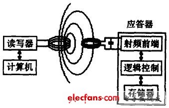
Figure 1 Schematic diagram of the RFID system 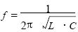
(where C is the parallel equivalent capacitance of Cp and C2'). The RFID application system realizes bidirectional data communication through this frequency carrier. The commonly used ID1 type non-contact IC card has a small plastic card (85.72mm × 54.03 mm × 0.76 mm), and the resonant frequency of the antenna coil is usually 13.56 MHz. The smallest area has been developed to be 0.4mm × 0.4 mm. Short-distance RFID application system for coil antennas. 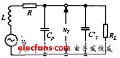
Figure 2 Transponder equivalent circuit diagram